


 Support Center
Sensing Differently
Table of Contents
Tuning features such as Bias Event Thresholds, Bias Filter Cutoff, Bias Refractory Period, and Region of Interest (ROI) allow for precise control over sensor sensitivity and response. Additionally, filters like the Anti-Flicker Filter, Event Burst Filter, and Event Rate Control (ERC) play a crucial role in reducing unwanted events. By adjusting these features, users can fine-tune sensitivity and eliminate redundant events, thereby limiting the output to only the most relevant data.
Before we delve into the details of these features, let’s first provide an overview of how conventional area scan cameras compare to the Triton2 EVS event-based camera, and explain how event-based sensors function.
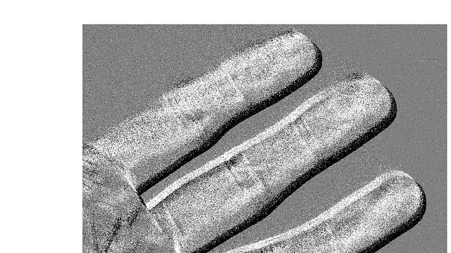
Area scan camera
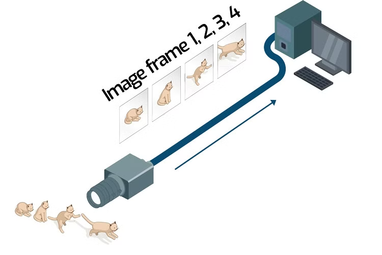
All pixels on the sensor capture light luminance either simultaneously (global shutter) or sequentially by rows (rolling shutter). The camera then processes this data to create image frames.
Event-based camera
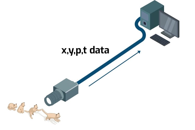
Each pixel operates independently, detecting changes in luminance (brightness) and outputs the coordinates (x, y), polarity (p), and timestamp (t) when the changes exceed a preset threshold. There is no concept of shutter or frame with event-based sensors and only pixels that detect changes send data, which reduces the overall output data.
How the Event-Based Pixel and Sensor Work
In an IMX636/637 event-based vision sensor, each pixel in the pixel array independently monitors the luminance of incident light. To do so, the pixel first converts the light it into a voltage. This voltage goes through a low pass and high pass filter which controls the frequency (time resolution) of contrast changes. The voltage is then compared to a reference voltage and the delta is calculated. The delta is then sent to a threshold check. This threshold check controls the level of contrast change that is allowed to pass. A positive event (dark to light) is generated if the luminance increases beyond the positive threshold, while a negative event (light to dark) is generated if the luminance decreases below the negative threshold. This positive or negative trait of the event data is called the polarity of the event. Upon generating an event, the pixel resets the reference voltage to the new luminance level. The animation below explains the major stages of the pixel processing along with the filter and threshold locations.
Side Note
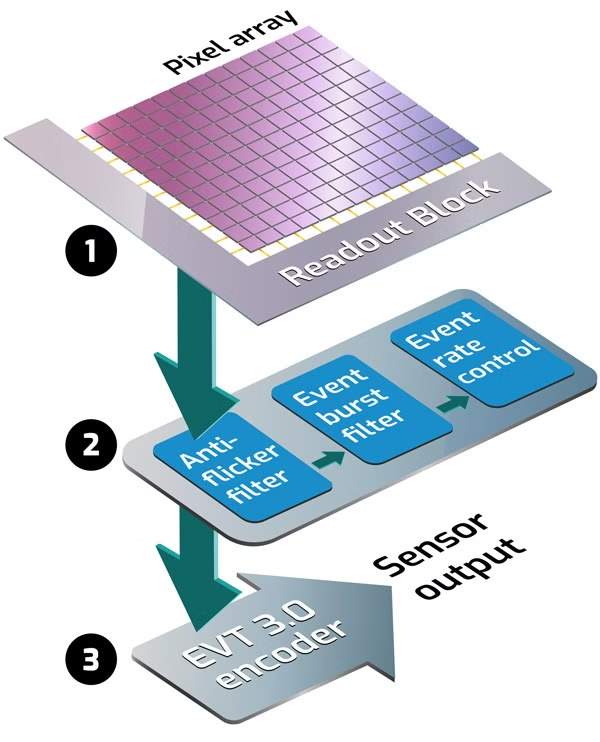
Once a pixel in the IMX636/637 sensor converts incident light into voltage, it is sent to the readout block:
1. The readout block adds X/Y coordinates and a timestamp to the events.
2. The signal processing block filters events (optional).
3. Event data is encoded in EVT 3.0 format and output.
2. The signal processing block filters events (optional).
3. Event data is encoded in EVT 3.0 format and output.
How Triton2 EVS works with PC software
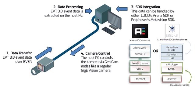
After processing the event-based signals through threshold filters, the events are sent through additional yet optional filters: anti-flicker filter, event burst filter, and event rate control. These filters are discussed in detail later in the article. After the events complete these filters, the Triton2 EVS camera encodes the event data into EVT 3.0*, a compressed 16-bit format devised by Prophesee. This data is sent over the network using the GigE Vision Streaming Protocol (GVSP), which is a standard for transmitting data over Ethernet for machine vision cameras.
When this data reaches the host PC, it is extracted and can be processed using LUCID’s Arena software development kit (SDK). The Arena SDK allows users to handle the event data in several ways: it can decode the XYPT format data for further processing, produce CD Frames (visualize the data via ArenaView), or it can keep it in its original EVT 3.0 format. Additionally, users have the option to use the Metavision SDK by Prophesee. When using the Metavision SDK, a HAL plugin for the Triton2 EVS translates the control commands into a format that the Triton2 EVS can understand. This means that users of the Metavision SDK do not need to worry about the specific details of controlling the Triton2 EVS, as the plugin handles that for them.
Finally, for controlling the camera and sensor, the GenICam nodes are used. GenICam is a standard that provides a generic programming interface for machine vision cameras, making it easier to control them in a consistent way, similar to how you would control a regular GigE Vision camera.
Visualizing Event Data: CD Frames
In the previous section, we mentioned that one of the ways LUCID’s Arena SDK can process the EVT 3.0 data is into individual image frames called a CD Frame (Contrast Detector Frame), which can be viewed using LUCID’s ArenaView GUI. CD Frames plot positive and negative events on a XY coordinate within a specific frame period. While this is the simplest and fastest way to visualize event data, the CD Frame has some limitations: it cannot represent multiple activations of the same pixel during the frame period, nor can it represent the timing within the frame period. Both ArenaView (part of the Arena SDK) and Metavision Studio (part of the Metavision SDK) can visualize event data using CD Frames.
In this video example, using ArenaView to display the CD frames, only a few events are detected because the target is stationary and there are minimal contrast changes occurring.
This video example shows a large number of events being detected due to a) the motion of the person and b) the large contrast of the black sweater to the white wall.

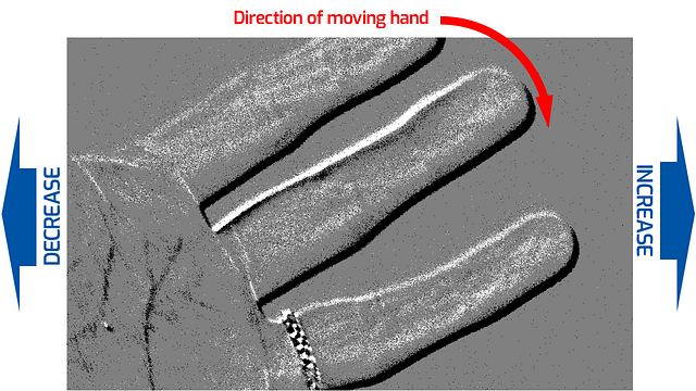
Generated events (contrast change) corresponds either to a positive event (dark to light) or a negative event (light to dark). This is known as the polarity of the event.
Bias and Filter Overview
In the sections below, we delve into the details of biases, filters, and other features of the Triton2 EVS camera that allow for fine tuning of events. The table below summarizes how each feature affects the camera’s output. You can click on the Bias / Filter name to jump to that specific section.
| Bias / Filter Name | Description | Bias Decrease / Filter Off | Bias Increase / Filter On |
|---|---|---|---|
| Bias Low Pass Filter Cutoff | Defines how the camera filters out rapid contrast changes. | Removes high-frequency changes. Increases latency. Reduces background rate, noise, and event rate. | Keeps high-frequency changes. Improves pixel latency. Increases the background rate. |
| Bias High Pass Filter Cutoff | Defines how the camera filters out slow changes in contrast. | Preserves low-frequency changes and slow motion. Increases event rate and noise. | Removes low-frequency signals. Removes slow motion. Decreases event rate and noise. |
| Bias Event Threshold Positive | Defines how sensitive each pixel is to positive contrast (dark to light) changes. | Increases background rate. Improves pixel latency. | Decreases sensitivity. Decreases background rate. Reduces event rate. |
| Bias Event Threshold Negative | Defines how sensitive each pixel is to negative contrast (light to dark) changes. | Increases background rate. Improves pixel latency. | Decreases sensitivity. Decreases background rate. Reduces event rate. |
| Bias Refractory Period | Controls the amount of time the pixel sleeps after an event. | Reduces the number of events triggered by a large contrast change. | Improves pixel availability. More events are triggered by a large contrast change |
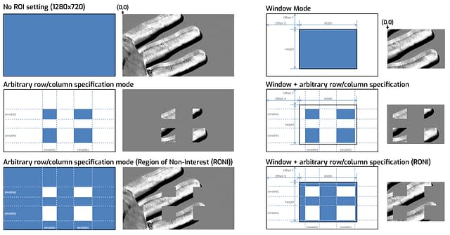
| Region of Interest (ROI) | Isolates width and height regions with X and Y offsets of the senor for sensing. Can also be inverted to mask sections. | The full resolution of the sensor is used to detect event data. | Can be used in Window Mode (one ROI region), Arbitrary Row/Column Specification Mode, or both. This reduces the overall event rate. |
| Anti Flicker Filter | Eliminate flickering in a specified frequency range. (ie from LEDs or fluorescent lights). | Flickering light is captured and increases event rate. | Flickering lights will be removed, reducing event rate. Filter can also be inverted to capture only the flickering light. |
| Event Burst Filter | Removes redundant events from a burst of events with the same polarity. | No events are filtered. | The TRAIL filter only outputs the first event of a burst. The STC filter outputs the second event of a burst or the second event to the end of a burst. |
| Event Rate Control (ERC) | Event rate control (ERC) drops events to keep the output event rate below the target event rate. | The camera processes all detected events. Can lead to data overflow if too many events saturate the data bandwidth connection. | Events are dropped if the rate exceeds the target during each 200 µs period after filtering. |
Bias Low Pass Filter Cutoff
Bias High Pass Filter Cutoff
To adjust the frequency of contrast changes that are detected, each pixel is equipped with a Bias Low Pass Filter Cutoff and a Bias High Pass Filter Cutoff.
The Bias Low Pass Filter Cutoff adjusts the cut off frequency of the low-pass filter, which determines how the camera filters out rapid contrast changes. Lowering this value removes high-frequency changes, increases latency, and reduces background rate, noise, and event rate. Increasing this value retains high-frequency changes, improves pixel latency, and raises the background rate.
The Bias High Pass Filter Cutoff adjusts the cut off frequency of the high-pass filter, affecting how the camera filters out slow changes in contrast. Lowering this value preserves low-frequency changes and slow motion, increasing event rate and noise. Raising this value removes low-frequency signals and slow motion, decreasing event rate and noise.
Adjusting the Bias Low Pass Filter Cutoff by decreasing it increases event latency and variation, while increasing it has minimal impact. Adjusting the Bias High Pass Filter Cutoff by increasing it reduces events caused by slow contrast changes. These adjustments help fine-tune the camera’s performance based on specific application needs, such as improving event detection accuracy or reducing noise.
Bias Low Pass Filter Cutoff Examples (Click images to enlarge)

Negative Value
(Decrease the value from default).
Decreasing the value reduces noise but leads to an increase in event latency and the variability in latency.

Default (=0)
In general, this functions similar to exposure time in a conventional area scan sensor, balancing the ability to capture fast motion against the increase in noise.

Positive Value
(Increase the value from default).
Increasing the value improves latency, however testing shows it doesn’t significantly increase noise from default.
Bias High Pass Filter Cutoff Examples (Click images to enlarge)

Default (=0)
Click to enlarge images

Positive Value
(Increase the value from default)

More Positive Value
(Increase the value from default)
By increasing the value, the number of the events caused by slow contrast change decreases.
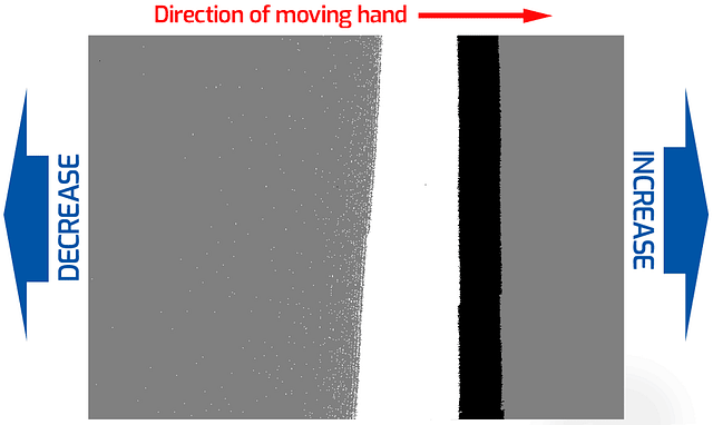
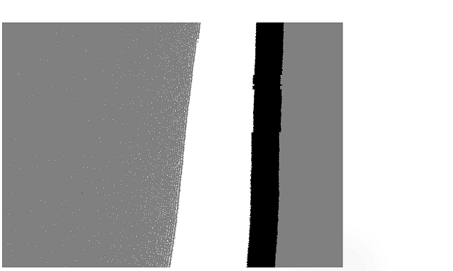
Bias Event Threshold Positive
Bias Event Threshold Negative
These two bias event thresholds determine the sensitivity to contrast changes, essentially setting the intensity of change needed for an event signal to be triggered. There are two main types of bias event thresholds: Positive and Negative.
The Bias Event Threshold Positive controls the sensitivity for ON events (how much of an increase in light is needed to generate a positive event), typically represented by white pixels. Decreasing this threshold value increases the number of positive events, resulting in more white pixels. Increasing this value decreases sensitivity, reducing the white pixels displayed.
The Bias Event Threshold Negative controls the sensitivity for OFF events (how much of a decrease in light is needed to generate a negative event), typically represented by black pixels. Decreasing this threshold value increases the number of negative events, resulting in more black pixels. Increasing this value decreases sensitivity, reducing the black pixels displayed.
For both Bias Event Threshold values, decreasing the value can improve pixel latency at the cost of increasing the event rate (more sensitive, detects smaller changes, more noise). Increasing the threshold values decreases sensitivity, helping to reduce the event rate (less sensitive, less noise, fewer events).
Bias Event Threshold Positive Examples (Click images to enlarge)
Negative Value
Higher sensitivity, more events, more noise.
Default (=0)
Controls how much of a light increase is needed for positive events.
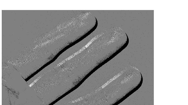
Positive Value
Less sensitivity, less events, less noise.
Bias Event Threshold Negative Examples (Click images to enlarge)
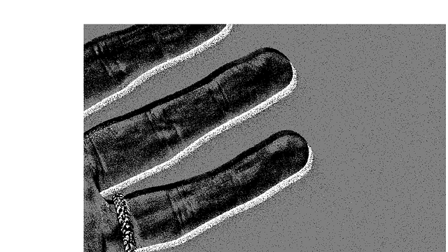
Negative Value
Higher sensitivity, more events, more noise.
Default (=0)
Controls how much of a light decrease is needed for negative events.
Positive Value
Less sensitivity, less events, less noise.
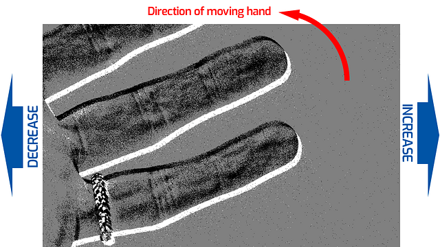
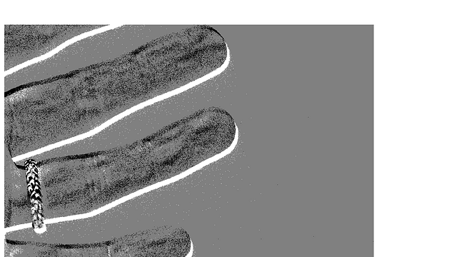
Bias Refractory Period
The refractory period determines how long a pixel remains inactive after detecting an event. This “sleep” period prevents the pixel from immediately responding to subsequent events, which can be particularly useful in environments with rapid or large contrast changes. By adjusting the refractory period, the sensor can control the number of events triggered by significant contrast changes. A longer refractory period reduces the number of events, while a shorter refractory period increases the number of events.
Bias Refractory Period Examples (Click images to enlarge)

Negative Value
Longer refractory (sleep) time
Default (=0)
Controls duration of sleep time between events.
Positive Value
Shorter refractory (sleep) time.
Region of Interest (ROI)
The Triton2 EVS offers two methods for specifying the Region of Interest (ROI). The first method involves defining a window ROI using parameters such as Width, Height, Offset X, and Offset Y, similar to the approach used in regular area scan cameras. This allows for precise control over one windowed area. The second method enables the multi ROI columns/rows feature (arbitrary row/column specification), which allows users to enable or disable individual rows and columns, providing greater flexibility in defining the ROI. Additionally, the system supports inverting the ROI (Region of Non- Interest, RONI), which functions as a mask to exclude unwanted regions from the analysis. This feature is particularly useful for focusing on specific areas of interest while ignoring irrelevant sections.
Anti Flicker Filter
The anti-flicker filter is designed to eliminate flickering lights within a specified frequency range. Flickering LEDs or fluorescent lights often generate numerous unnecessary events, increasing event data. By filtering out these unwanted events, the anti-flicker filter ensures that only relevant data is captured. Additionally, this feature includes an invert enable option that, when enabled, allows only flickering lights to pass through. This capability is particularly useful for focusing on a specific flickering light, enhancing the precision of light tracking.
Anti-Flicker Example (Click images to enlarge)
LED 50Hz Flicker
The LEDs and LED reflection circled here on the image are flickering at 50Hz.

Anti-Flicker Filter: OFF
With the filter turned off, the camera detects the flickering, generating around 1.2 Mev/s.

Anti-Flicker Filter: ON
With the filter turned on (49-51Hz), the camera removes the flickering, reducing the generated data to 20 Kev/s.
Event Burst Filter (TRAIL / STC)
This filter can be used to either remove redundant events from a burst or filter out the first event from a burst. A burst is defined as a series of repeated events with the same polarity (i.e., either positive or negative). There are two types of burst filters: TRAIL and STC (Spatio Temporal Contrast).
Event Burst Filter TRAIL Example
The TRAIL filter only outputs the first event of a burst. In addition, the Event Burst Filter Duration Reset Mode specifies if the duration to remove redundant events starts at the first event only (First Event of Burst), or if the duration for all events is to remove redundant events, including the duration for removed events (Every Event). Users can customize the duration for events. By eliminating redundant events, the TRAIL filter helps in reducing the overall data rate, which can be useful in systems with limited processing power or bandwidth.
Event Burst Filter STC Example
STC (Spatio Temporal Contrast) filter outputs only the second event of a burst (Second Event of Burst Only), or the second event to the end of a burst (Second Event of Burst to End). These filter settings are useful for applications that need to focus on significant changes in the scene while ignoring redundant events.
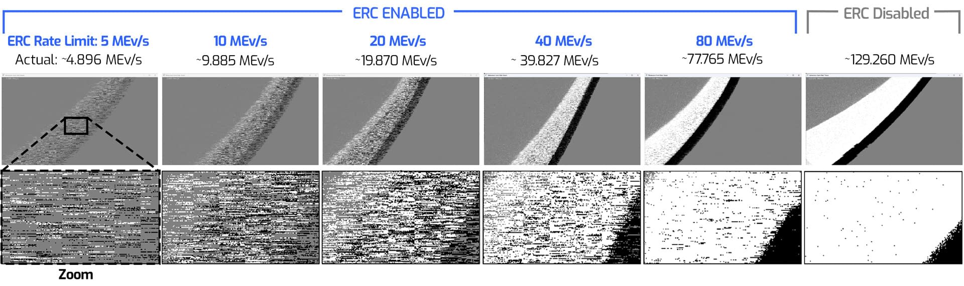
Event Rate Control (ERC)
Event Rate Control (ERC) is designed to manage the output event rate by dropping events when necessary to keep it below the target rate. This process occurs during each referencing period, which can be up to 200 microseconds, and takes place after the anti-flicker and event filters have been applied. Once ERC is performed, the event data is encoded using the EVT 3.0 format. The ratio between the event rate and the data rate can vary depending on other camera settings and scene conditions, making it challenging to adjust the data rate to a precise number.
The Triton2 EVS camera is designed to connect to the host PC at 2.5GigE as this bandwidth connection gives your system the greatest ability to handle events. However, there can be instances where extreme and prolonged spikes in contrast changes can flood the data bandwidth with events. In these cases, even on a 2.5GigE connection, setting an ERC limit can serve as a safety net against unexpected image latency, data overflow on the link, or the camera disconnecting due to spikes in events.
Conclusion
In this tech brief we’ve gone over how the Triton2 EVS event-based camera works and discussed many of the features and options that allow for fine-tuning event data for tailored results. In addition, tuning the camera can optimize the amount of data that is transferred to the PC, helping to reduce the overall CPU and memory resources used by the PC. Once fine tuning is complete, users can optionally perform a variety of custom processing tasks via Arena SDK or the Metavision SDK to enhance and analyze the data further. For more information, visit our Triton2 EVS product page.

Sources:
Sony: Event-based Vision Sensor(EVS)Technology
Sony: Event-based Vision Sensor (EVS) | Products & Solutions
Prophesee: Metavision SDK Documentation
A 1280×720 Back-Illuminated Stacked Temporal Contrast Event-Based Vision Sensor with 4.86µm Pixels, 1.066GEPS Readout, Programmable Event-Rate Controller and Compressive Data-Formatting Pipeline
How Neuromorphic Image Sensors Steal Tricks From the Human Eye
Retinomorphic Event-Based Vision Sensors: Bioinspired Cameras With Spiking Output
Latency Asynchronous Temporal Contrast Vision Sensor