Support Center
Active Sensor Alignment
Active Sensor Alignment
It allows vision application designers to reliably identify their optical specifications without having to worry about excessively tweaking and deviating from the original spec when they scale their application. For example, imagine producing multiples of the same vision application that inspects the same product but having to adjust the camera and optical setup to different specifications every time, or worse yet having to return and wait for a replacement camera because the optical specs are outside the tolerance levels. LUCID applies Active Sensor Alignment during the camera’s manufacturing process to minimize unit deviations and ensure quality imaging for each and every Triton, Atlas, and Helios camera unit, as covered by U.S. Patents 11,402,726 B2 and 11,599,009 B2.
Table of Contents
In a Perfect World...
In a perfect world, the sensor’s optical center, tilt, rotation, and back focal distance (BFD) would be the same for every camera unit. In this scenario the sensor placement would be specified and verified once and then applied to each future unit during manufacturing. In the real world however, there are slight differences in each of the components that make up a camera, including the angle, center and depth of the camera lens barrel as it relates to the position of the sensor on the PCB imager board.
Above: If all camera components were made perfectly, the sensor could be placed in the same exact spot for every unit.
Above: An exaggerated animation of some of the variables encountered with camera components. This leads to inconsistencies with accurate sensor placement inside the camera.
Challenges of Sensor Placement
Perhaps there is a tiny difference in one of the components, such as varying solder thickness under the image sensor or a tilted image sensor die within its package. While this difference might not be noticeable to the naked eye, their impact on image quality will be. This would lead to a difference in the back focal distance across the sensor area and, for example, produce a blurry corner in your image. The below animations are exaggerated examples of some the issues that vision application designers might encounter with poorly aligned camera sensors.
Left: Sensor tilt causes differences in focal points across the sensor plane. Center: Sensor rotation that is off-spec can add complexity to camera mounting. Right: Sometimes the lens barrel can be slightly off center, potentially darkening corners
Passive Sensor Alignment
The traditional method of aligning the sensor with the optical path relies on strict tolerances of the camera components. Camera manufacturers source components from multiple vendors and must ensure they meet their required specifications. The camera is then assembled with the hope that everything lines up. This is called Passive Alignment.
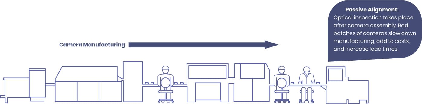
For passive alignment, to catch deficient cameras before being shipped, an image quality test is traditionally applied after the camera is manufactured. While this strategy can be effective, it is very time consuming and costly. Cameras that fail this test are already assembled, and the manufacturer must decide if these cameras are to be sent back and disassembled, inspected, remade, or thrown out. Furthermore, they must also inspect and identify the batches of components that led to these deficiencies. Ultimately, it forces tighter tolerances on the camera components, increasing cost and potentially waste. It is because of this that some camera manufacturers skip the inspection test entirely or instead, widen camera tolerances and ship out the cameras as-is to reduce costs at the expense of quality.
Active Sensor Alignment: Proper Placement at the Source
A much more accurate and efficient way of ensuring proper sensor placement is called Active Sensor Alignment. During the sensor placement process, the placement system measures image center, rotation, tilt and back focal distance, actively adjusting the sensor position based on feedback from visual measurements. The system employs an automated 6 degrees of freedom (6DoF) mechanical unit and a visual inspection unit. The visual inspection unit analyses a visual pattern overlayed across the sensor plane and measures the uniformity of the pattern’s sharpness. For example, if the system measures a corner that is slightly out of focus, it will adjust the sensor’s tilt until it is in focus. Once it calculates the maximum level of sharpness across the sensor plane, it will fix all the components in place.
Left: A light pattern is overlayed on the sensor. Any discrepancies in tilt, rotation, and depth will distort the light pattern. These distortions are measured and compensated for by moving the sensor using the 6DoF system (Right). From this, the sensor is tuned to the correct position in real time.
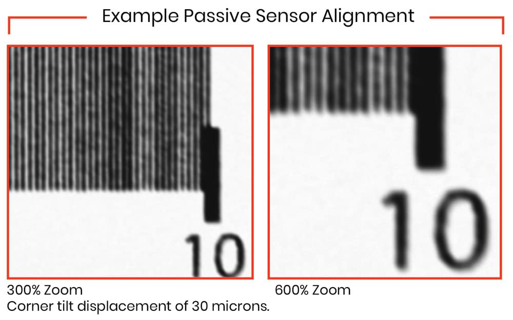
Simulated Example of a 30 Micrometer Corner Displacement
Below are simulated example images from a 12.3 MP Sony IMX304 CMOS 1.1” sensor using 6mm lens at f2.8. The passive aligned example image is simulated with a 30 micrometer corner displacement. Corner displacements for sensors can be caused by many things, including varying amounts of solder paste either inside or outside the sensor package. LUCID’s active sensor alignment system allows for precise micrometer adjustments to reduce these dependencies.


Looking at a cross section of the optical path, active alignment ensures the sensor is at the proper focal distance with equal distance from the center of the sensor to the edges.
Conclusion
Using this method allows for accurate sensor placement with a linear alignment and tilt resolution of micrometers. Smaller sensors benefit from precise centering. Having the center shifted even by a little bit can adversely affect the mounting placement of the camera. For larger sensors, minor changes in tilt can cause substantial differences in focal points across the image. For those vision applications that demand a high level of camera accuracy, Active Sensor Alignment is an important manufacturing step that ensures a accurate level of image sharpness than traditional passive alignment.