


 Support Center
™
The Factory Tough Camera
Factory Tough
Testing begins during the camera design and prototyping stage, where the camera hardware design is validated through multiple stress tests. During this validation phase, camera units are tested against extreme temperatures, physical shocks, continuous and random vibration, electromagnetic noise, power surges, and more. For some of these tests, units are sent to accredited 3rd party laboratories while other testing occurs in-house. Cameras are also tested and certified for international compliance in electromagnetic emissions, voltage levels, and hazardous substances.
Once the validation stage is complete, camera testing continues with unit testing during series production. During this phase, all camera units go through internal unit testing. These tests include thermal cycling functionality tests, ingress testing, sensor alignment tests, and EMVA 1288 image quality tests. All these tests ensure a flawlessly working factory tough camera in an industrial environment where a wide range of other machines, equipment, and electromagnetic interferences exist.
VALIDATION TESTING
Validation testing occurs during the camera prototyping stage, where camera prototypes are tested for proper functionality and robust design. These tests are meant to push the camera to the extreme limits, far beyond what would normally be encountered during regular operations. Validation tests help pinpoint any weakness in the design before series production begins. Any weaknesses exposed from the tests initiate an investigation and ultimately a redesign. After which the redesigned camera is sent back and retested until it passes.
Extreme Temperature Cycling
What does it do?
It tests the camera’s design against extreme hot and cold temperatures within a thermal chamber. The hot and cold temperatures are significantly higher than the thermal shock tests that occur during unit testing. During the tests, the camera cycles through functionality tests such as power cycling and image streaming.
Standard: None, but HALT (Highly Accelerated Life Testing) is used as a framework for prototype testing.
Why is this important?
This stage helps identify any weaknesses in the camera before series production begins. During the testing, cameras are monitored for any failures allowing engineers to improve and fix any issues. This type of test helps reduce any design flaws from reaching production models.

Thermal Shock Chamber
Thermal test chambers allow cameras to be tested in extreme hot and cold chambers. The cameras are rapidly moved between the chambers via an internal platform.
Shock / Impact / Vibration (Random) Testing
What does it do?
It tests the camera’s ability to withstand physical shocks (also known as pulses). The cameras are mounted to a shock testing machine (electrodynamic shaker) that produces pulses at different frequencies and at different severity along the X, Y, and Z axes.
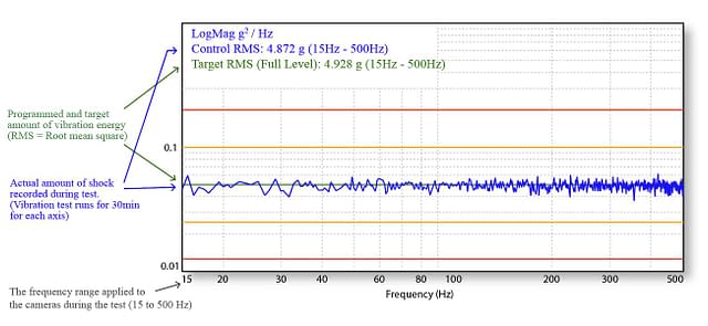

Example of random vibration and shock recording.
The electromagnetic shaker measures and reports the test results. After testing, the cameras showed no physical damage and produced normal images during standard operation.
Standard: IEC / DIN EN 60068-2-27 Environmental testing – Part 2-27: Tests – Test Ea and guidance: Shock. IEC / DIN EN 60068-2-64 Part 2-64: Tests – Test Fh: Vibration, broadband random and guidance.
| Test | Standard | Parameters |
|---|---|---|
| Shock | DIN EN 60068-2-27 | Each axis (x/y/z), 20g, 11ms, +/- 10 shocks |
| Bump | DIN EN 60068-2-27 | Each axis (x/y/z), 20g, 11ms, +/- 100 bumps |
| Vibration (random) | DIN EN 60068-2-64 | Each axis (x/y/z), 4.9g RMS, 15-500Hz, 0.05g2/Hz acceleration, 30min per axis |
Why is this important?
Industrial machines work within a complex system of many moving parts. Cameras mounted on moving parts are exposed to abrupt changes in direction as well as accidental impacts. For machine vision cameras, shock and vibration testing validates the structural design of the camera. This not only tests the ruggedness of the internal components inside the camera but also the camera’s mounting design and lens mount strength. Cameras that can withstand shock and vibration are beneficial in many applications outside of industrial manufacturing, such as automotive (uneven roads) and mobile robotics (path-finding collisions).
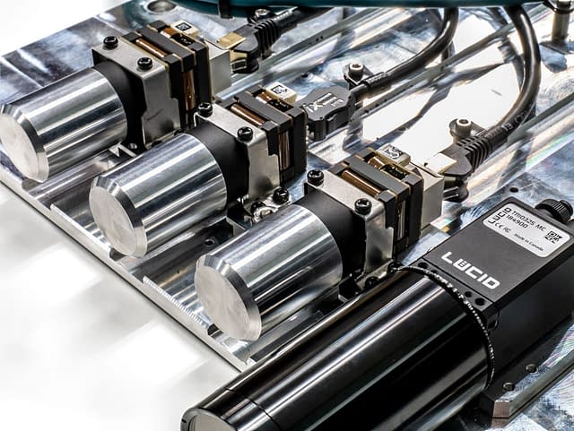
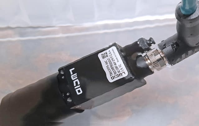
LUCID cameras prepared for vibration testing.
LUCID cameras are secured to an electrodynamic shaker. This electro-dynamic shaker controls the amount and duration of the shock and vibration. The cameras are connected to PCs for live monitoring. Dummy lenses are also attached to simulate real world operation.
Vibration (Sinusoidal) Testing
What does it do?
It tests the camera’s ability to withstand harmonic patterns of vibration. This test is very intense on the camera, with the electrodynamic shaker vibrating at levels that produce sound loud enough to require ear protection. The electrodynamic shaker runs through harmonic frequency from low to high (58 to 500 Hz for LUCID cameras, with a sweep rate of 1 octave per minute) at 10 g peak (20 g peak-to-peak). This is done for X, Y, and Z axes.
Standard: IEC / DIN EN 60068-2-6 Environmental testing – Part 2-6: Tests – Test Fc: Vibration (sinusoidal).
| Test | Standard | Parameters |
|---|---|---|
| Vibration (sinusoidal) | DIN EN 60068-2-6 | Each axis (x/y/z), 10-58 Hz: 1.5mm, 58-500 Hz: 10g, 1 oct/min, 1 hour 52 min per axis |
Why is this important?
While application engineers do their best to reduce application vibration, machinery, engines, motors, and other moving parts will always produce some level of vibration. Rotating, pulsating or oscillating forces will emit harmonic vibrations. Some of these harmonic vibrations can be constant and go undetected by the human eye. Sinusoidal testing exposes any weakness in the camera design due to resonances. A resonance in the design can result in a disproportionate stress on the camera when the shaking frequency matches the resonance. An example of a design feature susceptible to resonance would be a tall component on a PCB that can oscillate like a diving board.
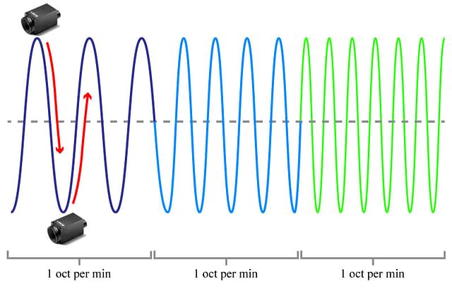
Sweep Rate
The sinusoidal vibration frequency moves up an octave per minute in this test. This is known as the “sweep rate”.
EMC Testing (Electromagnetic Compatibility)
What does it do?
It tests the camera’s immunity against electrostatic discharges and electromagnetic interference in industrial environments. The camera is exposed to electromagnetic noise, power surges, voltage dips and other interferences. This is to ensure the device will operate as intended and without failure when used within industrial environments.
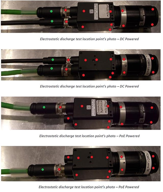
Electrostatic discharge immunity
While the camera is powered and streaming, a specialized ESD gun is used to discharge voltage at certain points on the camera. This test has the potential to damage electronics and interrupt data transmission. In the example below, the Triton camera suffered no degradation in performance.
Standard: IEC / DIN EN 61000-6-2 (Generic standards – Immunity standard for industrial environments)
Why is this important?
Without proper EMC industrial immunity testing, there is no guarantee a machine vision camera will survive the electromagnetic interference of an industrial environment. These environments contain a variety of motors, power systems, and devices that produce greater levels of electromagnetic interference compared to residential or commercial environments. This test ensures that the camera can withstand stronger electromagnetic fields, higher conducted noise levels, bigger power surges, and larger electrostatic discharges while being fully operational and streaming images.
| What exactly is tested for EN 61000-6-2 EMC immunity? |
|---|
| Radio frequency electromagnetic field immunity. (DC and PoE): 80 – 1000MHz @ 10 V/m 1400 – 2000MHz @ 3 V/m 2000 – 2700MHz @ 1 V/m |
| Radio-frequency common mode (AC mains and Ethernet): 0.15–80MHz, 10 VRMS, 3s dwell time |
| Surge immunity (DC and PoE): Up to ±2 kV |
| Electrical fast transients – burst immunity: AC Input: Up to ±2 kV Ethernet Port: Up to ±1 kV |
| Voltage dip and short interruption immunity at power ports (DC and PoE): 30%, 60%, 100% Voltage reduction |
| Electrostatic discharge immunity: 50 direct discharges (25 of each polarity) up to ±8 kV for contact and ±15 kV for air |
Sources of electrostatic discharges & electromagnetic interference:


EMI Testing (Electromagnetic interference)
What does it do?
In the previous pages we focus on the limits of what the camera can handle. But we also have to test and measure what’s being emitted from the camera, specifically electromagnetic fields and disturbances that can interfere with other devices while in use. There are global standards that limit the strength of these emissions. These standards must be met before any camera, as well as any electrical device, can be sold to the public in a specific region.
Standard: IEC / DIN EN 61000-6-3 (Part 6-3: Generic standards – Emission standard for equipment in residential environments), FCC Class A (Commercial/Industrial, USA), FCC Class B (Residential, USA), CE (EMC 2014/30/EU)
Why is this important?
Poorly designed devices will emit strong EMI and fail compliance testing. Failure can signify a number of issues – low quality components, bad component placement, lack of grounding, power supply inefficiencies and more. Having a camera compliant with these standards helps to validate the camera design, one that is optimized, power efficient, and safe to work with other devices while operating.

EMI Compliance Symbols
FCC and CE markings will be placed on the product, either on a product label or etched on to show EMI emissions compliance.
UNIT TESTING
Unit testing refers to quality assurance tests that are applied to each camera unit during series production. Unit testing helps verify consistent camera functionality, performance and screens out any units with defects or performance anomalies.
Thermal Shock Testing
What does it do?
Each camera is tested in a heat chamber that alternates between hot (upper limit) and cold (lower limit) temperatures. The upper and lower limits are set slightly beyond the camera’s defined operating temperature specification to ensure the camera reaches the correct limits. Functionality tests run periodically throughout thermal cycling. Some examples of functionality tests include power cycling (on/off), sustained image streaming and grabbing, image chunk CRC checks, and signal to noise ratio (SNR) checks. Bit errors are checked, and power consumption levels are monitored to make sure they stay within tolerance levels. This thermal cycling is repeated several times over many hours.
Example of thermal cycling testing and monitoring
During thermal shock testing, the cameras are tested and monitored. This helps detect and screen any defect cameras.
| Green Dot = Camera Functionality Test |
|---|
| Power Cycling (on/off) |
| Image Streaming |
| Image Chunk CRC |
| Signal to Noise Ratio (SNR) |
| Bit Errors |
| Power Consumption |
Standard: None, but HASS (Highly Accelerated Stress Screening) is used as a framework for unit testing.
Why is this important?
Temperature cycling helps to screen for defective camera units before reaching the customer. It also ensures that each camera unit will perform properly without any issues within the defined operating temperature.
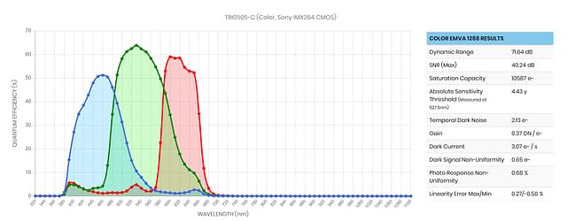
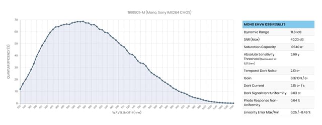
EMVA1288 Image Quality Threshold Tests (Image Performance Tests)
What does it do?
Each camera is tested on a flat-field light device to measure image quality based on EMVA 1288 standards (EMVA: European Machine Vision Association). Test results must reach a level of quality that are within acceptable tolerances. Results for temporal dark noise, saturation capacity, photo response non-uniformity, dark signal non-uniformity, and linearity error are measured.
Standard: EMVA Standard 1288 – Standard for Characterization of Image Sensors and Cameras.
Why is this important?
It ensures that camera units of the same model have consistent image quality performance from unit to unit. Any unit that does not reach the image quality thresholds is removed and sent for further testing. In addition, almost all camera manufacturers perform image quality tests based on the EMVA 1288 standard. This allows users to view a standardized set of image quality results between different camera sensors and across multiple camera manufacturers.
| Example Test criteria for Triton 5.0MP |
|---|
| Temporal dark noise: Less than 2.4 e- |
| Saturation capacity: Greater than 9500 e- |
| Photo response non-uniformity: Less than 3% |
| Dark signal non-uniformity: Less than 1.5 e- |
| Linearity error Less than 1% |
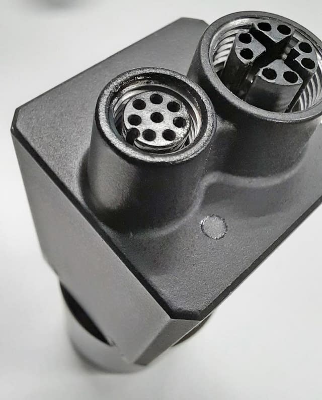
GPIO Signal Tests
What does it do?
The GPIO input and output signals are tested for correct voltage thresholds. Appropriate voltage signals are sent to the camera to trigger a successful image grab.
Standard: None, however, 24V PLC logic level support in the Triton, Atlas IP67, and Helios2 allows for higher voltage signaling in noisy industrial environments.
Why is this important?
Machine vision cameras are often used in conjunction with other devices on the factory floor. These devices are synchronized to either trigger the camera or vice versa, with the camera triggering the external device. For input signals, it is important that the camera can be set to receive a higher threshold voltage for triggering as industrial environments can cause false triggering due to their higher levels of electrical noise. To allow for this, the Triton and Helios2 camera contain an adustable threshold level for reliable triggering within noisy environments.
Active Sensor Alignment
Sensor to Mounting Flange Alignment Test
What does it do?
Measures the sensor tilt, image center to lens mount and back focal distance (BFD).
Sensor tilt causes differences in focal points across the sensor plane.
Sometimes the lens barrel can be slightly off center, potentially darkening corners.
Sensor rotation that is off-spec can add complexity to camera mounting.
Standard: None, however, Active Sensor (optical) Alignment during the sensor placement stage measures the placement in real time to ensure proper sensor placement for every unit.
Why is this important?
As opposed to traditional mechanical sensor placement, which uses shims and passive placement techniques, Active Sensor Alignment ensures that sensor placement is correctly aligned to the lens barrel. This is critical for clear and sharp imaging across the sensor plane, from the center to the edge of the sensor. This produces consistent image quality from unit to unit, allowing application engineers to design in a camera confidently without having to worry about camera adjustments for each application unit.
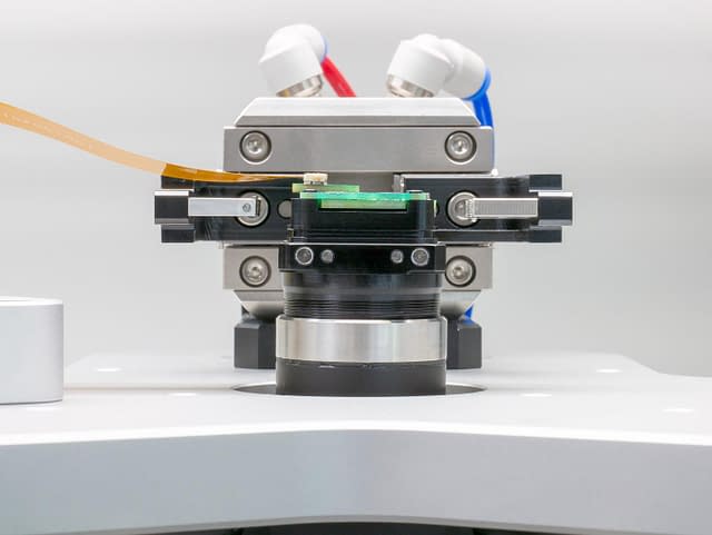
Active Sensor Alignment Device
In this image, a Triton unit is having the sensor aligned and fixed on to the lens barrel of the camera.
IP67 Testing (Dust and Water Ingress)
What does it do?
It tests the protection of the camera’s case against intrusion of dust and water. Pressure and water submersion tests are done.
Standard: IP67 (IEC standard 60529) dictates that the camera must have no ingress of dust (dust proof) and be water proof up to 1 meter (3 ft 3 in) in depth for 30 min.
Why is this important?
For any electrical device, dust and moisture can have very harmful effects. This is even more pronounced in industrial environments, where machines that cut, scrape, and wash down products are used. Fruit and vegetable processing plants, for example, bring in dust particles from the soil and moisture from water sprays. To maintain reliable camera operations, it is important to choose an IP67 camera. In addition, while external IP67 enclosures have been around for some time, having IP67 protection built into the camera enables better use of application space. Without the need for additional IP67 enclosures, application designers can build a more compact system, with reduced assembly time and easier maintenance.
Ingress Test
All Triton, Altas IP67, and Helios2 units go through IP67 water ingress testing.
Triton/Triton2/Triton10 IP67 GigE, Atlas/Atlas10 IP67 5GigE, Helios2 3D ToF Cameras
Not all machine vision cameras are built to withstand the harsh environments of industrial factories. While many camera manufacturers might say their cameras are ready for 24/7 industrial operation, certain criteria and standards must first be met through proper testing and reporting. It can be time consuming to sift through the vast array of camera specifications from camera maker to another, thus, the greatest challenge in choosing a factory tough camera is in knowing what the right testing standards are and what they mean. This tech brief serves as an overview to these tests, and while it’s not exhaustive in listing all the potential tests available (such as for medical or military use), it does introduce the most common testing and camera specifications specifically designed for industrial environments.
LUCID has leveraged its vast experience in machine vision camera design to deliver factory tough cameras. In particular, the Triton, Atlas IP67, and Helios2 cameras are built for harsh industrial use as it is certified with EMC industrial immunity, shock and vibration certification, and IP67 dust and water protection. By creating innovative cameras built to withstand the challenges of industrial use, LUCID enables vision application designers to build the most robust and lasting vision applications for their customers.