


 Support Center
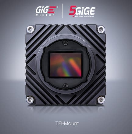
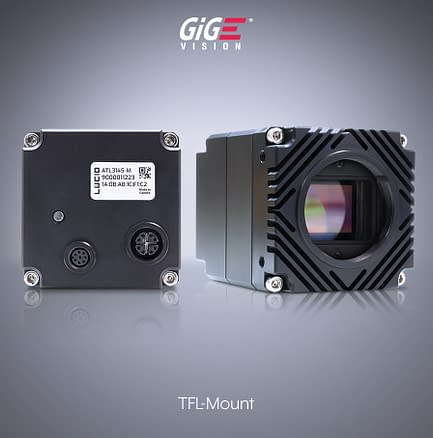
Filling the Gap Between C-mount and F-Mount
Table of Contents
There are three ways that sensors can increase their resolution: sensor can grow in size while pixel size remains the same, pixel size can get smaller while sensor size remains the same, or a bit of both (example below). There are tradeoffs with each of these methods; typically, smaller pixels tend to mean a lower signal to noise ratio (SNR) when compared to larger pixels, but larger sensors tend to be more expensive. The general trend, however, shows sensor sizes increasing, even as pixels continue to decrease in size. The machine vision industry is at an interesting time currently, with sensor sizes maximizing what a C-mount is physically capable of. C-mount is a camera standard that defines a 25.4 mm threaded mount with a back flange distance (often referred to as a flange focal distance or simply flange distance) of 17.526 mm.
Above: Sensors are getting bigger in size through adding more pixels, as well as increasing in resolution by decreasing pixel size.
Reaching the Limits of C-Mount
As shown in Figure 1, below, the maximum diameter that an optic can achieve in a C-mount housing is around 17 mm, despite its opening being 25.4 mm. This is due to the fact that the lens has mechanics of its own that need to accommodate the main lens barrel, the focusing inner barrel, and a retainer to hold the optics in place. Each of these steps reduce the size of the available clear aperture of the optical elements in the lens assembly. As the size of the optics decreases, the angle at which the light must come out of the lens grows. This is not a problem when sensors are smaller than the size of the optics, but as sensors increase in size, it becomes more difficult for the optics to pair up well with the sensor inside of a C-mount. As this angle (θ in Figure 2) increases, the corners of the image become much darker due to cos4(θ) roll-off. Figure 2 shows this fall-off relationship with respect to the angle. In addition, the image sensor itself has a roll off depending on how the pixel’s micro-lenses are optimized. Because of this it is of high priority to minimize this angle in an optical design. All of this together essentially makes 1.1″ format (17.6 mm diagonal) the practical sensor size limit for the best performance in a C-mount camera.
Figure 1, Left: The cross-section of the back of a C-mount 1.1” high resolution 12 mm focal length lens. Due to supporting mechanics the maximum lens diameter of the last lens is smaller than the 25.4 mm C-mount opening. This results in steeper ray angles for larger sensors which can affect brightness (above right graph) (Red lines represent light rays for the corner of a 1.1″ sensor, Brown lines represents 1″ sensor, Blue lines represent the sensor’s center.)
Figure 2, Right: The impact of chief ray angle on relative brightness on an image sensor. Steeper angles reduce brightness on the edges unless mitigated with more costly optics. Large sensors in C-mount cameras exacerbate this problem.
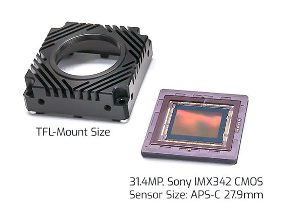
The third generation release of Sony’s Pregius came with the IMX342, which is a 31.4 MP sensor in an APS-C format (27.9 mm diagonal). This sensor is far too large for a C-mount. However, it is in an interesting space for the industrial camera marketplace, as this sensor is too small for an F-mount (M42), which is the next size up and has several optical problems associated with it. M42 is a potentially logical option, and cameras already exist with an M42 lens mount, though there exists no commonly accepted standard that the camera industry adheres to make this option viable (with varying flanges and thread pitches). TFL, however, is the perfect mount for a sensor of the APS-C size and is standardized through the Lens Working Group of the Japan Industrial Imaging Association (JIIA). A TFL-mount is M35x0.75 mm, with a 17.526 mm flange distance; this is the same flange distance as the C-mount. Because of this, it can be thought of as a larger diameter C-mount.
TFL-Mount vs F-Mount
The TFL-mount has several advantages over F-mount for an APS-C sensor size. These advantages are in cost, flange distance, and the way that the lens is secured into the lens mount on the camera. F-mount lenses are larger compared to TFL-mount lenses. This is mostly due to the fact that they are meant to cover much larger sensors (up to 43.3mm diagonal vs APS-C 27.9mm diagonal). As lenses grow in size, they grow more expensive as well; a rough rule of thumb would indicate that the cost for a single lens element grows with the radius squared. Extrapolated over several elements, it is easy to see how larger lenses are more expensive.

Figure 4: TFL-mount gives enough space for surrounding lens mechanics for APS-C sensors, which reduces issues created from steep ray angles.
Flange Distance Matters
Another major advantage of the TFL-mount solution over an F-mount solution is the flange distance. As mentioned above, the TFL-mount can be thought of as a larger diameter C-mount because they share the same flange distance of 17.526 mm. F-mount has a flange distance of 46.5 mm. The long flange distance of the F-mount limits the type of optical design form that can be used. This is especially true for shorter focal length lenses, which tend to have shorter back focal lengths (BFL, not to be confused with a flange distance, the back focal length is the distance from the last optical element to the image plane). Making a short focal length with a long BFL forces the lens to be designed as a reverse telephoto, which is to say a lens with a focal length that is shorter than the overall length of the lens. Forcing a lens into this design paradigm inherently causes tradeoffs to be made with the design in terms of resolution. This can, in certain circumstances, be overcome with lenses that have a larger rear protrusion, meaning that the lens protrudes into the camera housing. However, lenses with large amounts of rear protrusion tend to need to reduce their diameters substantially in order to properly fit inside the camera body, leading to the same cos4(θ) issues listed above. The shorter flange distance of the TFL not only contributes to an overall shorter system, but allows the optical engineer a lot more freedom when designing to maximize the resolution of the lens.
This smaller flange distance, coupled with the fact that TFL lenses will be designed for smaller sensors and hence be less impacted by field-dependent aberrations, means that lenses designed for TFL-mount cameras will be higher performing in a smaller package size, and will be more cost-effective.
Above: Camera cut-out illustration comparing the flange distance between C-mount, TFL-mount, and F-mount and its affect on camera size.
Threaded vs Bayonet
F-mount is not a threaded screw mount; rather, it is a bayonet mount. Bayonet mounts are great for photography, as they allow the user of the camera to swap lenses out quickly for different scenarios, and allows for the easy integration of electronic features (iris/focus control) since they are a clocked mechanism. However, for the majority of applications in machine vision, these advantages are not really advantages. Lenses are rarely (if ever) replaced, and if they are it is not in a time sensitive manner. Iris control is useful in corner case applications, but it is usually fixed, and relying on servomotors/micro motors with moving parts to focus a lens in a factory environment millions of times is likely going to lead to parts wearing out.
The major disadvantage of the bayonet mount, however, is simply the nature of the bayonet mount itself. As sensors grow in size, the amount of allowable tilt of the sensor with respect to the optical axis becomes smaller. Figure 5 shows how tilt in the image plane with respect to the optical axis impacts larger sensors more. Keeping the tilt numbers small is imperative to ensuring high optical performance, especially given low f/#s, which are required for high resolution applications. The bayonet mount allows for more tilt in the imaging system, and doesn’t pair the lens and camera together in an optimal way. This is mostly due to the fact that the tolerances of the Nikon F-mount are not published numbers, so optics companies can be left guessing what the tolerances should be for their designs. In contrast, threaded screw mount flanges are machined into a solid piece of metal and can be made very flat. Furthermore, the clamping force of threaded screw mounts are vastly stronger than a bayonet. The lens flange and camera flange are held flush together without wobble or sag even with vibration or gravity regardless of the lens size. TFL is also a published standard and a threaded mount, meaning that both camera and lens companies know exactly what to design so that they work together in the most efficient way possible.
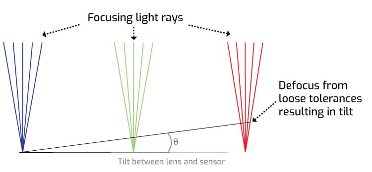
Figure 5: As sensors grow larger in size with smaller pixels, keeping tight tolerances are imperative. A bayonet lens connection allows for a looser connection to the camera compared to the TFL threaded connection. This could result in a less focused image.
Click to enlarge
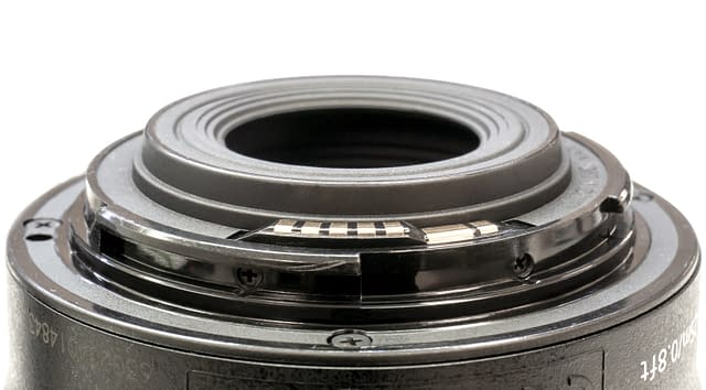
Above: Bayonet lens mounts are great for photography but their added components, multiple parts, spring-loaded clip connection, and lack of published specification standards introduces uncertainties for industrial applications needing 24/7 operation.
Click to enlarge
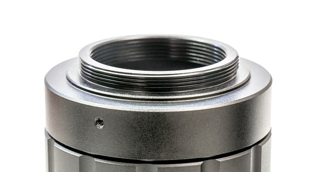
Above: Threaded screw mounts (TFL lens shown above) are machined into a solid piece of metal allowing for vastly stronger clamping force with the camera. This eliminates wobble or sag even with vibration or gravity regardless of the lens size. TFL is also a published standard.
TFL-Mount + Active Sensor Alignment
The perfect lens mount with the perfect lens will not mean much if the camera’s sensor is not precisely aligned to the lens barrel. To maximize the value and performance of a high quality TFL lens with a TFL-mount camera, active sensor alignment is needed to ensure that the sensors are centered and placed correctly within the camera without tilt or rotation. This procedure is even more critical for sensors larger in size and with smaller pixel sizes, as these two characteristics make sensors more sensitive to micrometer placement discrepancies. As highlighted above in Figure 5, a tilt of only a few micrometers can effectively defocus a high resolution lens on a large 4/3″or APS-C sensor. LUCID’s active sensor alignment system measures image center, rotation, tilt and back focal distance. It actively adjusts the sensor position during placement based on feedback from visual measurements. Using an automated 6 degrees of freedom (6DoF) mechanical unit along with a visual inspection unit the system analyses in real time a visual pattern overlayed across the sensor plane. This pattern is measured for maximum sharpness ensuring a uniform sensor plane while the sensor is fixed into place. Read our tech brief on LUCID’s Active Sensor Alignment technology used in both our Atlas and Triton cameras.
Above: LUCID’s Active Sensor Alignment ensures that the sensor is centered and placed in the optimal position, without tilt or rotation, to the lens barrel. This ensures an optimal path for light to travel, through the lens to the sensor, with maximum sharpness from the center to the corners of the sensor.
Above: An exaggerated animation of some of the variables encountered with camera components. This leads to inconsistencies with accurate sensor placement inside the camera.
TFL-Mount for Machine Vision Cameras
With TFL-mount lenses being smaller, lighter, less expensive, and designed for long term performance in industrial operations, they are certainly the better choice for sensors larger than 1.1″ and up to APS-C size. While the standard is still gaining in popularity within the machine vision marketplace, they are a promising new take on the optics and cameras that are used every day. Sensors will, of course, continue to evolve, and camera lenses will continue evolving right along with them. More and more industrial sensors are entering the market beyond 1.1″ and with smaller pixel sizes, such as Sony’s 4th gen Pregius S 24.5 MP IMX530 CMOS, a 4/3″ sensor (diagonal 19.3mm) with a 2.74µm pixel size (37% smaller pixel size vs 3.45µm) as an example. These sensors will be best handled by pairing a high quality TFL lens with an actively sensor aligned TFL-mount camera, such as LUCID’s high resolution camera family – the Atlas.
For more information, explore these TFL-mount products.
-
Atlas 16.8 MP Model (IMX387)
Register or login for pricing -
Atlas 19.6 MP Model (IMX367)
Register or login for pricing -
Atlas 31.4 MP Model (IMX342)
Register or login for pricing -
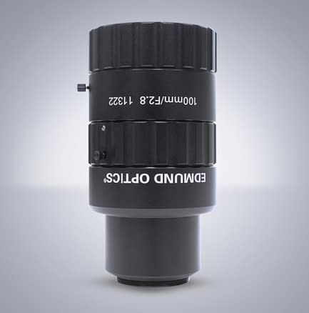
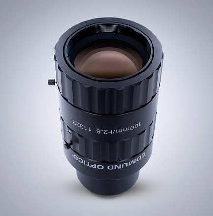
Edmund Optics TFL-Mount APS-C 100mm f/2.8
Register or login for pricing -
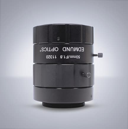
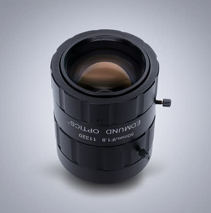
Edmund Optics TFL-Mount APS-C 50mm f/1.8
Register or login for pricing -
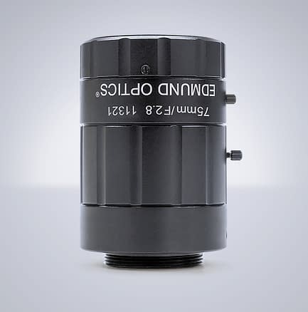
Edmund Optics TFL-Mount APS-C 75mm f/2.8
Register or login for pricing