Support Center
Sony’s Polarized Sensor: Beyond Conventional Imaging
Polarization - A Property of Light
Application engineers can take advantage of polarization cameras by filtering unwanted reflection or glare as well as enhancing contrast by colorizing polarized angles of light. Different materials used in products can reflect and alter the properties in light. Whereas normal colour and mono sensors detect the intensity and the wavelength of incoming light, the special polarized sensors used inside polarization cameras can detect and filter angles of polarization from light reflected, refracted, or scattered off surfaces. To understand some of the benefits our Phoenix and Triton polarized cameras using Sony’s polarization technology, called Polarsens™, let us first expand on what polarized light is.
Table of Contents
Polarization – A Property of Light
Good Vibrations: Unpolarized to Polarized
Polarization From Polarizers
Polarization From Reflection
Polarization From Refraction
Taking Advantage of Polarization
Existing Polarization Solutions
Polarsens: How Sony’s Polarized Sensor Works
Extinction Ratios
Phoenix & Triton with IMX250MZR/MYR CMOS
Video Presentation – Adding a New Perspective to Industrial Imaging
More Polarization Resources
Good Vibrations: Unpolarized to Polarized
Polarization is a fundamental property of light and describes the direction in which the electric field of light oscillates. The majority of light sources, such as the sun, emit unpolarized light. Unpolarized light has vibrations at randomly oriented directions perpendicular to the direction of travel. For light to be polarized randomly oriented vibrations are removed or transformed into either a linear, circular or elliptical electromagnetic wave. For the examples below, we will only discuss how unpolarized light is linearly polarized.
Side Note
While incoming light with polarized angles perpendicular to the polarizer plane will be blocked, other polarized angles will instead be transformed into a lesser magnitude polarized wavelength. In the example below angled light is not blocked out but instead transformed to lesser magnitude linear polarized light.
Polarization from Polarizers
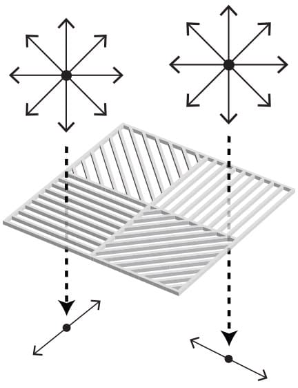
When this light hits a linear polarizer, such as the vertical and horizontal polarizers in the example below, the angled vibrations are filtered out with only vertical or horizontal vibrations passing through. When light vibration is restricted to one plane it is called linearly polarized. There are different types of polarizers with the most common ones being crystalline, dichroic, film, and wire-grids.
Above: Example of Vertical and Horizontal Polarizers
Note: In the example above the line patterns on the film polarizers represent their polarizing angles and not physical wire-grid lines
Polarization from Reflection
Unpolarized light can be polarized through surface reflection of non-metallic surfaces. Metallic surfaces reflect the polarization of the incident light, either polarized or unpolarized and do not significantly polarize. Other materials such as semi transparent surfaces of glass, plastics, and water reflect and polarize a certain amount of light back into the environment. This reflected light causes undesirable glare depending on the position of the user or camera. However, because the reflected light is polarized perpendicularly to the plane of incidence, it can be removed by using a polarizer aligned parallel to the plane of incidence.
Polarization from Refraction
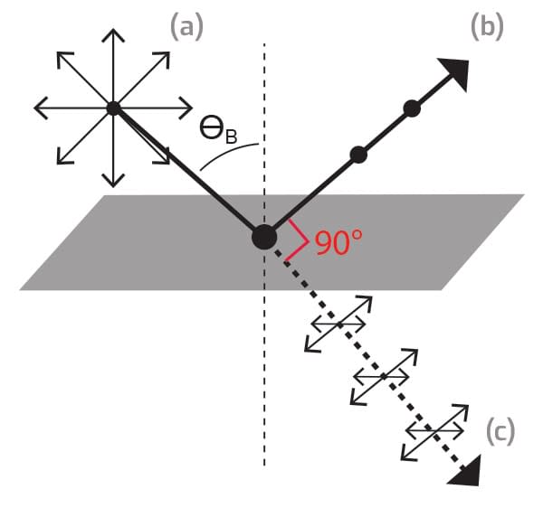
The passing of light through one medium to another, known as refraction, can also cause some of the unpolarized light to become polarized. The amount of light that is polarized from refraction depends on how near or far it is from Brewster’s angle (a 90° relationship between the reflected and refracted light). Transparent materials such as glass, plastics, and water can partially polarize refracted light to the plane of incidence.
Above: Unpolarized Light Becoming Polarized by Reflection
Side Note
If a beam of unpolarized light (a) strikes a surface so that there is a 90° angle between the reflected (b) and refracted beams (c), the reflected beam will be linearly polarized. The refracted beam will be partially polarized. The angle of incidence where the reflected and refracted beams are perpendicular to each other is known as the Brewster angle.
Taking Advantage of Polarization
The applications of polarization have long been used in machine vision inspection to detect stress, inspect objects, and reduce glare from transparent objects. The typical setup would require one or more external polarizer plates between the target object, light source and camera. Various setups can be used to measure material stress, enhance contrast, and analyze surface quality for dents or scratches.

Stress Inspection
When polarized light passes through transparent materials, the incoming angle of polarized light will be transformed to a different angle by different areas of stress in the object. By assigning a color to specific angles of polarization, defects and areas of stress can be visualized. The above object shows a colorized image of a clear acrylic block.
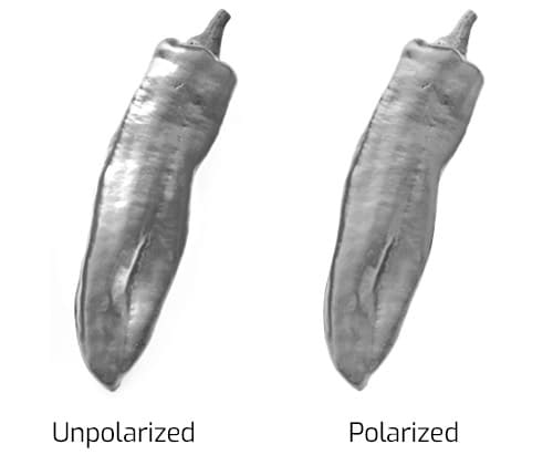
Reduce Reflection
Objects can reflect light and make it difficult for surface inspecting. Food inspection applications can benefit from the use of polarizers by reducing reflection and glare. In the image above, polarized reflected light is removed from the pepper.
Improving Contrast
In low light situations, contrast can be improved by detecting the angle of polarization off objects. The above example demonstrates how contrast is improved from regular imaging in low light.
Scratch Inspection
Similar to stress inspection, certain imperfections and scratches can be difficult to identify using conventional imaging. To help identify surface defects, polarized imaging can be used to detect scratches on transparent materials.

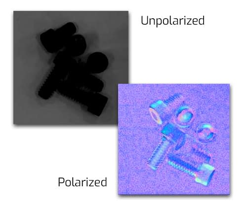
Object Detection
In some scenarios it can be hard to distinguish objects from their environments. Using polarized imaging can locate objects by detecting the unique polarized angle of reflected light from the object.
Existing Polarization Solutions
3 Cameras
Switch
Trigger Source
Host PC
• Perspective distortion
• Expensive
• More development effort
• More maintenance effort
3 Polarizers
1 Camera
• Needs to have high speed flipping
• Time delay between polarizers
Sony IMX250MZR polarized sensor
• Complete linear polarization data
• Overall system cost-saving
• Low effort for development


Sony's First Polarized Sensor: How It Works
Sony expands their sensor technology leadership beyond visible imaging with their first ever polarized sensor using their Polarsens™ technology. Built upon their Pregius 5.0 MP IMX250 CMOS sensor, the new IMX250MZR (mono) Polarsens sensor incorporates a layer of polarizers above the photodiodes. The polarizer array layer is placed on-chip and is an air-gap nano wire-grid coated with an anti-reflection material that suppresses flaring and ghosting. This on-chip placement reduces polarization crosstalk and improves extinction ratios.
The polarizer array is comprised of four different angled polarizers (90°, 45°, 135° and 0°) which are placed on each pixel. Every block of four pixels makes up a calculation unit. The relationship between the different directional polarizers in this innovative 4 pixel block design allows the calculation of both the degree and direction of polarization.
Side Note
Wire-grid polarizers polarize light perpendicular to the wire-grid lines. Polarized parallel light is reflected and adsorbed by the wires while perpendicular light passes through.
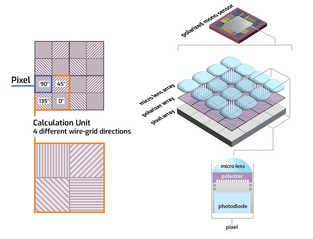
Above: Sony’s Polarsens 4 Pixel Block Polarizer Design
Sony’s IMX250MZR 4 pixel block, known as a calculation unit, allows for the detection of all linear angles of polarized light, not just 90°, 45°, 135° and 0°. This is possible through comparing the rise and fall in intensities transmitted between each pixel in the 4 pixel block.
Above: The 90°, 45°, 135° and 0° pixels are each measuring polarized light (rotating red line) in relation to their wire-grid axis. The percentage represents the rise and fall of light transmission (100% equals maximum transmission). By comparing each pixel with each other the sensor can detected all angles of linear polarized light.
The polarizer array is positioned on-chip as opposed to on-glass. With the position of the polarizer array being on-chip and below the micro lens, Sony’s polarization sensor is able to reduce crosstalk from polarized angles being incorrectly detected by the wrong pixel.
Above: 0° polarized light is entering the pixel meant to detect 90° and will be incorrectly detected as 90°. This crosstalk error happens because the polarization array is placed above the micro lens.
Above: Sony’s polarization sensor reduces the chance of crosstalk thanks to the polarizer array being placed on-chip. The 0° polarized light is unable to enter the pixel meant to detect only 90°.
Extinction Ratios
An extinction ratio represents the relationship between the maximum and minimum amount of transmitted polarized light through a polarizer. For a linear wire-grid polarizer, the maximum transmission of polarized light occurs perpendicular to the wire-grid axis. As this perpendicular angle of polarization rotates 90°, we hit the minimum transmission point which occurs parallel to the wire-grid axis. No polarizer is perfect. At the angle of maximum transmission there will be some loss and at the angle of minimum transmission there will be some unwanted angles that transmits through. High extinction ratios allow better detection of a desired polarized angle without other polarized angles mixing in.
Above: The maximum transmission (T max) and minimum transmission (T min) are used to calculate the extinction ratio
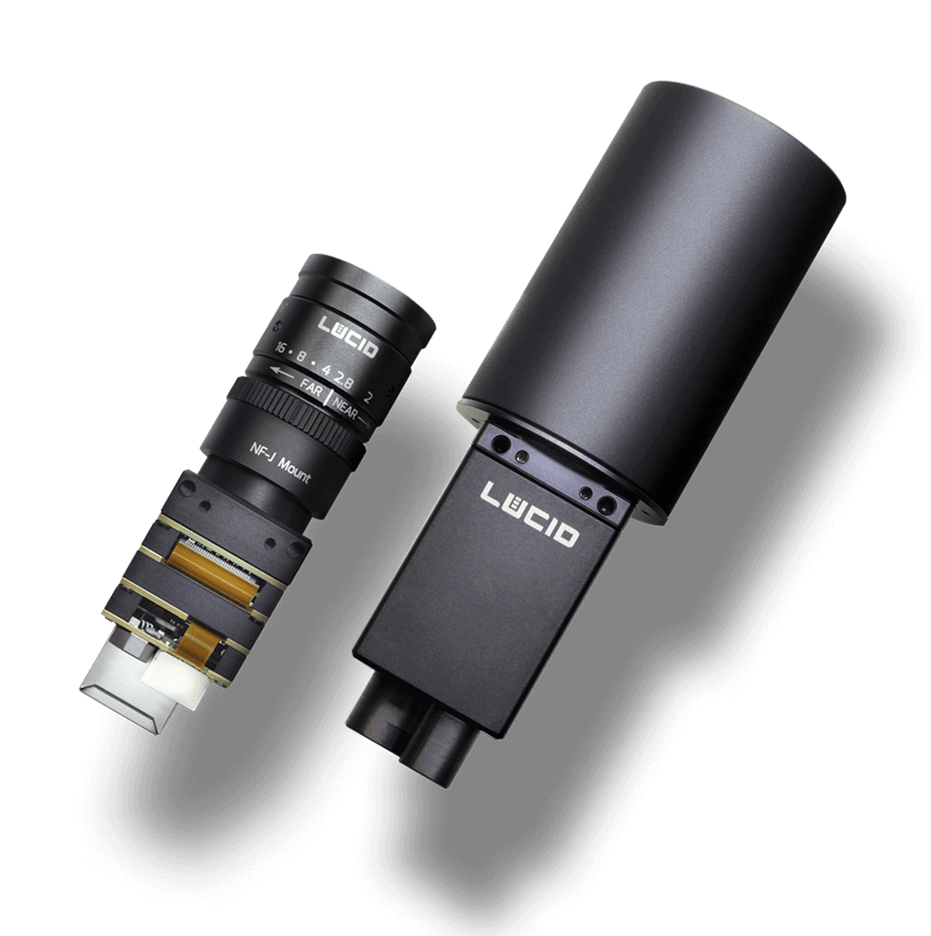
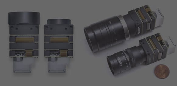
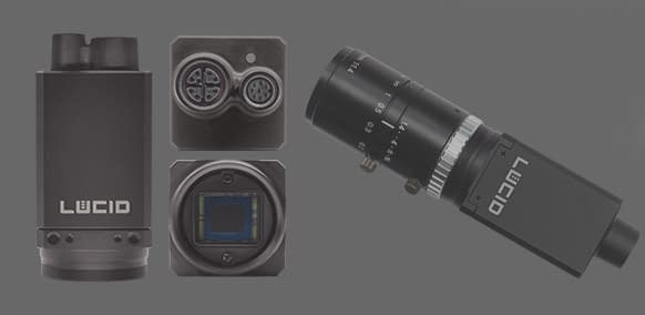
Phoenix and Triton using Sony's IMX250MZR CMOS (Mono) IMX250MYR CMOS (Color) with Polarsens Technology
With the help of polarization cameras, many material properties that were impossible to identify with conventional RGB sensors can now be easily acquired. The 5 MP global shutter sensor with a pixel size of 3.45µm is based on the popular IMX250 Sony Pregius CMOS mono sensor with the addition of an on-chip nanowire polarizing layer. This combination is Sony’s Polarsens technology and it provides excellent imaging performance, accurate polarization data, and high extinction ratios. LUCID’s Phoenix and Triton cameras featuring Sony’s IMX250MZR and IMX250MYR CMOS polarized sensors provides on-camera processing using the four directional filters and outputs both the intensity and polarized angle of each image pixel. With combining of these innovative products, polarization can now be a compact and cost-effective way to solve imaging challenges and uncover hidden material properties to better perform inspection and classification.
Video Presentation - Going Polarized: Adding a New Perspective to Industrial Imaging

Download PDF Presentation File Going-Polarized-Presentation.pdf (4 MB)