


 Support Center
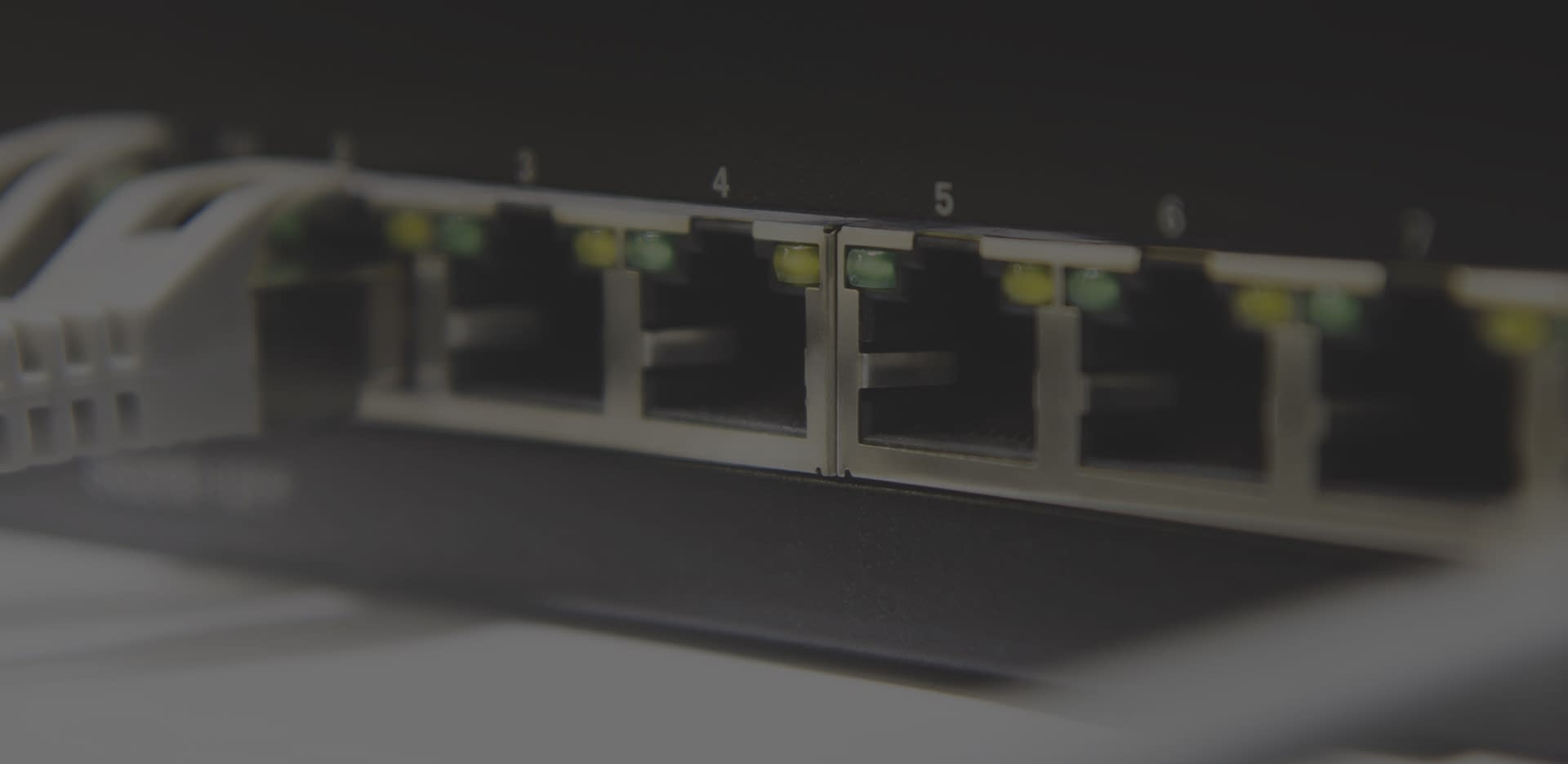
Gigabit Ethernet:
The Efficient and Reliable Interface
The Leading Industrial Interface
Every year, more and more users are choosing Gigabit Ethernet, or GigE for short, as the main camera interface for their vision application. A combination of increased system flexibility, readily available components, low cost 100m cabling, and industry standard adherence has led GigE to be one of the dominant interfaces in the machine vision camera world. Since 2006, GigE cameras have steadily grown in market share with current estimates at over 50% for deployed machine vision systems.
Table of Contents
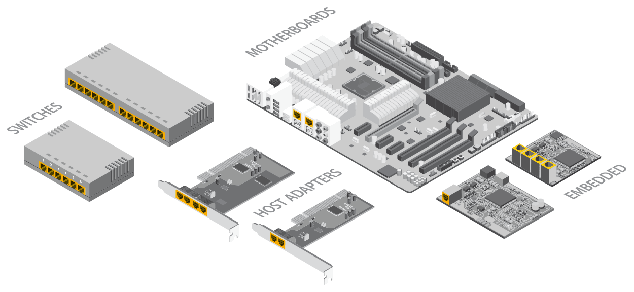
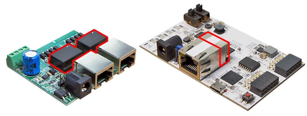
Above: A Wide Range Of GigE Components Are Readily Available
Multi-Point Control and Flexibility
Ethernet’s growing uptake in the industry was helped by its multi-point distribution flexibility and low cost 100 meter cable length. Unlike point-to-point interfaces that are designed for connecting peripherals to PCs over short distances (< 10m), Ethernet was developed to network multiple computers in a scalable and standardized way across rooms, floors and entire buildings. Since first being standardized in 1983, the Ethernet standard includes speeds of up to 40 Gbps and even 100 Gbps! While those high speeds are mainly reserved for major IT and data center networks, higher bandwidth Ethernet cameras are beginning to make their way into the vision industry and current mainstream 1 Gbps machine vision cameras continue to grow in number. A massive and diverse range of standardized Ethernet hardware are also easily accessible, allowing for greater choice in system design and costs. With 100-meter cable lengths users can vary camera distances or opt for even longer distances with additional Ethernet switches. In addition, cameras, switches, and interface cards that support Power over Ethernet (PoE) simplify cabling and maintenance by pushing power and data through the same cable. All of this combined allows for greater user flexibility in multi-camera application design.
Side Note
Always check the IEEE power standard on the PoE switch or interface card to ensure enough power is delivered to all PoE cameras. IEEE defines them as follows:
IEEE 802.3af Type 1-15.4W
IEEE 802.3at Type 2-30W
IEEE 802.3bt Type 3-60W
IEEE 802.3bt Type 4-100W
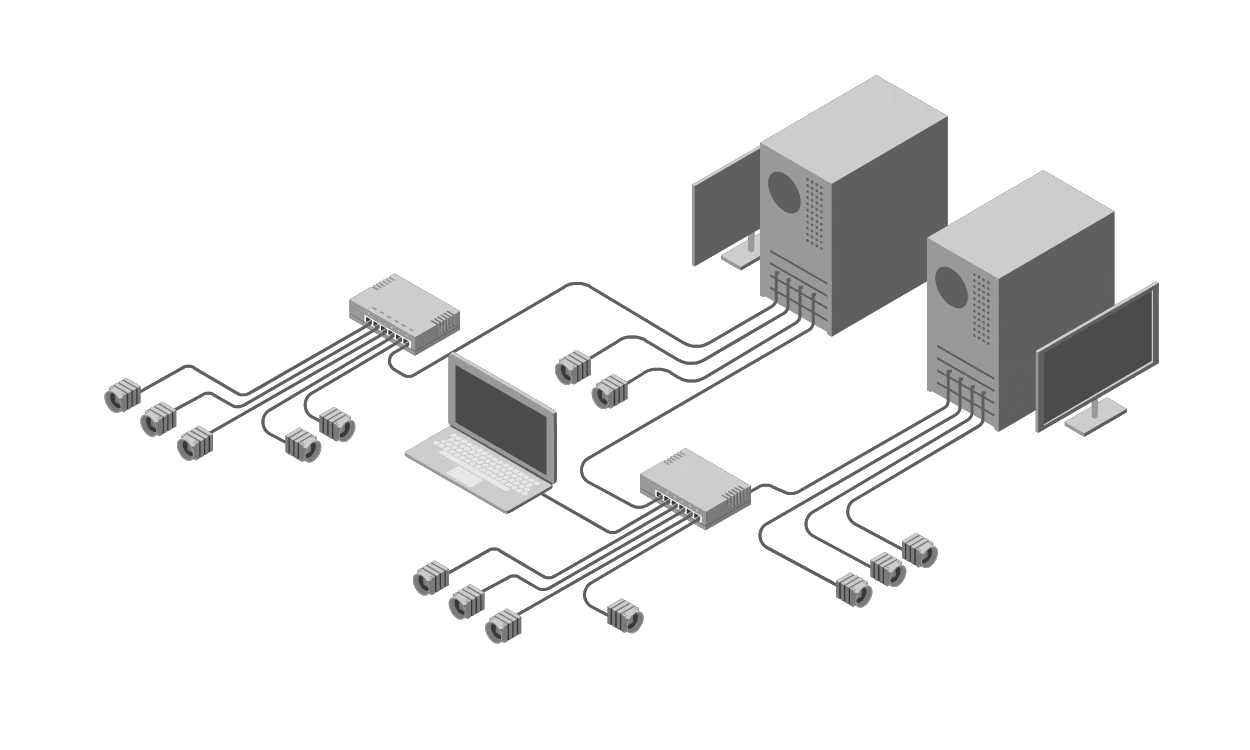
Above: Ethernet Allows for Diverse Multi-Point Applications
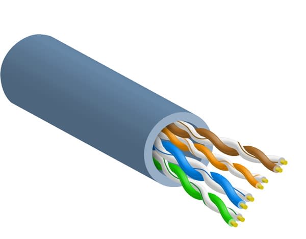
EMI Shield: Cat 6a Cabling
As demands for increased bandwidth continue in industrial environments, standardized improvements for Ethernet cabling are evolving to guarantee higher speeds maintaining noise immunity and to control emissions. Cat 6a cables continues the 100 meter cable length tradition but allows for frequencies up to 500 MHz which enables 10 Gbps data rates. Cat 6a cabling minimizes crosstalk by using larger-diameter conductors, tighter twists, pair separation, and a thicker outer jacket. For noisy industrial applications with many EMI sources such as noise from lights, machinery, and adjacent cabling, as well as RFI from cell phones and wireless networks, there are shielded cable options to mitigate EMI and RFI noise effects. Moreover, as pair-to-pair coupling and crosstalk becomes a limiting factor at 10 Gbps rates, Cat 6a cables are available with individually shielded pairs within the cable to improve signal quality at those data rates. All Cat 6a cables can be terminated in the field using regular or shielded RJ45 connectors.
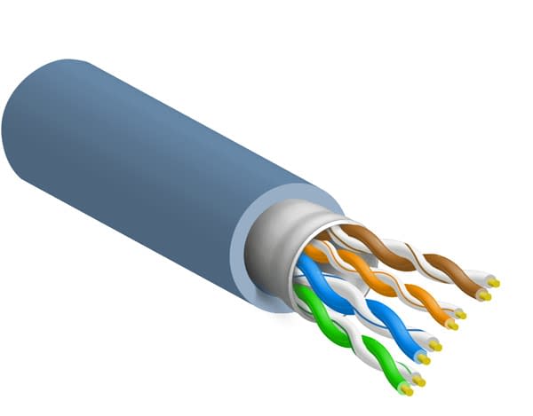
Cat 6a U/UTP
Category 6a U/UTP cables consist of 4 unshielded twisted pair (UTP) elements and no outer shielding (U).
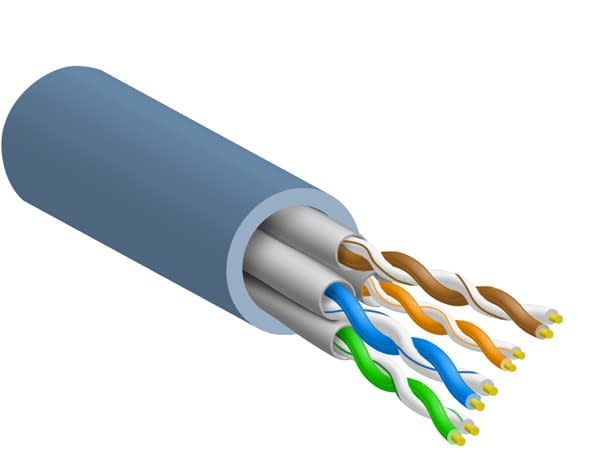
Cat 6a S/UTP, SF/UTP
Category 6a shielded UTP cables have a single or dual layer shielding using foil screen and/or metal metallic braid extending over the group of unshielded twisted pairs.
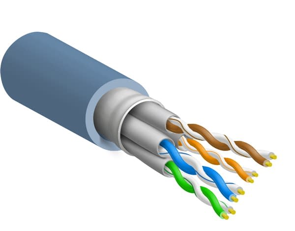
Cat 6a STP or FTP
Category 6a shielded twisted pair (STP) or foiled twisted pair (FTP) cables have individual shielding around each twisted pair using either a foil screen (FTP) or metallic braid (STP).
Cat 6a SFTP
Category 6a shielded foiled twisted pair (SFTP) cables have two layers of shielding – one around the entire group of twisted pairs and an individual screen layer for each pair.
Side Note

Maximum cable lengths (without using extenders)
GigE: 100 m
CoaXPress: 130 m
Camera Link: 10 m
Camera Link HS: 15 m
USB 3.1: 3 m
No Common Ground
Industrial motors and relays can create switching noise, while power cables adjacent to data wiring can couple noise and hazardous voltages into connected equipment and devices. Moreover, differences in ground potentials between devices and equipment in industrial applications can result in ground loop currents leading to further noise and EMI issues. To ensure proper functioning and operation of critical equipment and to minimize safety hazards in industrial environments, isolation techniques are employed to prevent current flow between connected devices while allowing data transfer. The Ethernet standard was designed to reduce those risks from the very beginning. Ethernet uses transformers on both sides of the connection, effectively isolating connected devices. Because of this, GigE Vision cameras do not share common ground, reducing the risk to camera and connected equipment.
Above: Transformers (red) are built into the Ethernet standard. Transformers can be external to the connector or included inside the connector.
High Standards
For the machine vision industry, Gigabit Ethernet standards play a key role in the growth of GigE cameras. Adherence to the GigE Vision™ and the GenICam standards have made the GigE eco-system extremely interoperable between hardware and software vendors. Compatibility and usability between vendors has increased, improving the user experience and offering wider consumer choices.
GigE Vision was introduced in 2006 by the Automated Imaging Association (AIA). The standard works to unify integration and communication protocols over Ethernet between cameras, hardware components, and software packages. For example, 3rd party software that is GigE Vision compliant will work with any camera that is also GigE Vision compliant. The GigE Vision contains 4 components:
- GigE device discovery, which provides a way to obtain IP addresses (persistent IP, DHCP, link local addressing).
-
GigE Vision control protocol, which runs on the UDP protocol. The standard defines how to control and configure devices. It specifies stream channels and how image and configuration data between cameras and computers are sent.
-
GigE Vision stream protocol, which also runs on the UDP protocol, defines the data types and the ways images can be transferred.
-
An XML description file based on the GenICam standard (see right).
GenICam was introduced in 2006 and ratified in 2008 by the European Machine Vision Association (EMVA). The goal of GenICam is to standardize the user application programming interface by defining how to configure the camera, grab images, send extra data, and perform events. It also includes a standard feature naming convention (SFNC) for camera features. This helps create a more consistent user experience across camera vendors. The GenICam standard consists of 3 main standards:
- GenApi standard provides a generic programming interface for cameras.
- GenCP standard defines the control protocol for GenICam cameras.
- GenTL standard provides a generic way to enumerate devices, communicate with other devices, if possible, and stream data to the host computer.
Thanks to these two machine vision standards users can build and expand their applications with less time and less worry. GigE Vision makes it easier to connect devices and control them with 3rd party software. GenICam greatly reduces the learning curve associated with using different vendor software by creating a generic and predictable user experience.
Increased Reliability with Packet Resends
Because low latency and fast transmission speeds are very important for GigE Vision applications, GigE Vision sends packets using the UDP protocol instead of TCP. UDP removes most of the error-checking and all negotiation time between devices and hosts to maximize speed. While UDP is faster than TCP, it does not include the same level of reliability for packet delivery as TCP provides. To help mitigate this, the GigE Vision standard adds a header to the UDP packet containing the image number, packet number, and timestamp information. This header information is used to place packets in order if they arrive out of order. Users can also set a time limit on how long to wait for a delayed packet until a resend signal is sent for that missing packet.
Side Note
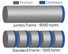
To maximize GigE bandwidth it is important to increase the packet size. Enabling and setting Jumbo Frames, which have a packet size of 9000 bytes, reduces the amount of overhead versus the default packet size of 1500 bytes.

Above: Missing Packets Are Requested And Placed In Proper Order
In the example above an image is sent from the camera to the host in 5 packets. The packets arrive out of order and packet 3 fails to arrive. A packet resend is then requested and packet 3 is resent and delivered. The 5 packets are then arranged in order. While this resend process greatly helps transmission reliability it is not required for GigE Vision compliance, therefore it is important to choose a camera with this feature if data transmission is critical.
Reliability Through Spectral Avoidance
The massive growth of wireless devices in the ISM (industrial, scientific and medical) unlicensed spectrum can lead to significant interference between devices and affect the connection reliability of your machine vision camera. Wi-Fi, Bluetooth, Zigbee, cordless phones, microwaves, and certain power sources can emit RF signals in 2.4 GHz frequency range. Vision applications where devices are closely packed together can fall victim to different levels of interference. Unlike other interfaces, such as USB 3.1, which can respond to interference or interfere with services operating in the 2.4 GHz range, Ethernet operates at a much lower frequency. Gigabit Ethernet signaling operates at 125 MHz rate, making GigE Vision cameras and Ethernet components unlikely to respond to interference or interfere with wireless devices. While interference mitigation techniques such as shielding, channel selection, and distance placement are possible, the easiest method to improving application reliability is avoiding interference in the first place.
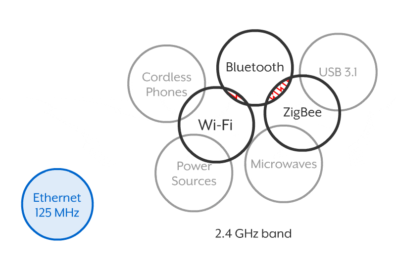
Above: Ethernet Operates at 125 MHz (Blue). Billions of Wi-Fi, Bluetooth, & Zigbee Devices Use the 2.4 GHz Spectrum (Black). Other Devices Use or Interfere With The 2.4 GHz Spectrum (Grey).
On Time and Ready for Action
Precision Time Protocol (PTP), also known as IEEE 1588 standard, is a packet-based technology that synchronizes devices connected to a network. The GigE Vision 2.0 standard incorporates PTP IEEE 1588 technology, making all GigE Vision 2.0 and PTP enabled cameras and devices easier to synchronize over the network to within microseconds of each other. Users can employ greater operational precision between cameras, sensors, triggers, motors and controllers leading to lower jitter and faster application speeds.
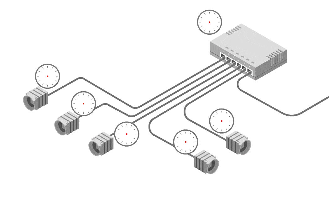
Clock Synchronization of PTP Enabled Devices
Synchronization is achieved by first determining which device on the network will act as the master clock to the other devices (which will act as slave clocks). Packets are sent back and forth in a session between all PTP devices and an algorithm determines which will be the master clock. In the example above the PTP switch is chosen as the master and all other devices sync to its clock.
Because of PTP, it is possible to utilize scheduled action commands and enable synchronous free run between all networked cameras. Schedule action commands allow users to schedule precise software triggers and remove the need for hardware triggers, further simplifying application design and maintenance. Synchronous free running allows multiple cameras to synchronize their shutter timing to within sub-microseconds of each other. When a scheduled action command is initiated, all the cameras will trigger at the same time. With PTP, it is possible to have cameras throughout the factory floor with synchronized timestamps, operating and inspecting products within sub-microseconds, and triggering without additional external triggering devices and cables.
The Future of Ethernet
| Standard | Function group | Title |
|---|---|---|
| IEEE 802.1AS-Rev | Timing and Synchronization | Timing and Synchronization for Time-Sensitive Applications |
| IEEE 802.1Qbv | Forwarding and Queuing | Enhancements for Scheduled Traffic |
| IEEE 802.1Qbu | Forwarding and Queuing | Frame preemption |
| IEEE 802.1Qca | Stream Reservation (SRP) | Path Control and Reservation |
| IEEE 802.1CB | Stream Reservation (SRP) | Seamless Redundancy |
| IEEE 802.1Qcc | Stream Reservation (SRP) | Enhancements and Performance Improvements |
| IEEE 802.1Qci | Forwarding and Queuing | Per-Stream Filtering and Policing |
| IEEE 802.1Qch | Forwarding and Queuing | Cyclic Queuing and Forwarding |
| IEEE 802.1CM | Vertical | Time-Sensitive Networking for Fronthaul |
| IEEE 802.1Qcr | Forwarding and Queuing | Asynchronous Traffic Shaping |
| IEEE 802.1CS | Stream Reservation | Local Registration Protocol |
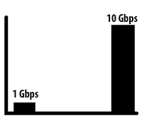
2.5GBASE-T and 5GBASE-T
The final approval of the 2.5GBASE-T (2.5GigE) and 5GBASE-T (5GigE) standards took place in 2016. With an estimated 70 billion miles of CAT5e/CAT6 cabling already deployed, existing GigE infrastructure can now easily take advantage of these increased speeds. The additional speeds of 2.5 Gbps and 5 Gbps not only gives users flexibility in their upgrade path but also allows for faster throttling speeds for those already using 10 GigE cameras. If a 10 GigE camera can not auto-negotiate 10 Gbps connection it can fall back on 5.0 and 2.5 Gbps connections.
Cloud Computing
Cloud computing is growing exponentially thanks to its low-cost and scalable services. Ethernet provides a low latency and more secure way to connect to cloud services and data centers than regular internet access. Not only is Ethernet pertinent for creating fast and secure Local Area Networks (LAN) but also across Metropolitan Area Networks (MAN). Ethernet allows for multiple large scale vision inspection points, such as a city wide ITS application, that can quickly and reliably access cloud services for image analysis or storage.
Industrial Internet of Things (IIoT)
As the miniaturization of computing continues, computers that once fit into desktop towers now can fit into machine vision cameras. With already a wide range of smart cameras available, more and more of the image analysis and processing are being shared between the camera, the host, and the cloud. For critical industrial applications, connecting the camera to other IIoT devices as well as to the host and the cloud requires a fast, secure, and deterministic connection. Ethernet serves as the best possible solution for future IIoT vision applications.
Conclusion
The case for choosing Ethernet is strong and compelling. While other interfaces might offer higher bandwidths at the moment, application designers must also consider system flexibility, overall costs, application reliability, and future technologies. Today’s application designers have to think a step ahead. That means planning to not only transform today’s legacy GigE infrastructure to 2.5 Gbps, 5.0 Gbps and 10 Gbps, but what implications that transformation will have on expanded networks with higher numbers of connected cameras and devices, increased cloud access for storage and analysis, and more on-camera processing with reduced system hosts. By choosing Ethernet now for current vision applications, designers can help ensure a smooth transition to future beneficial technologies while maintaining overall system reliability and increased deterministic operations. It is useful to know that some of these technologies do not involve entire system redesigns. With an Ethernet based application, engineers can safely plan future designs without worrying about radical changes to the Ethernet landscape.