


 Support Center
Making Inroads into High Speed Vision
Table of Contents
Like every other networking and interface standard, Ethernet has evolved from supporting data rates over ranging from the now obsolete 10BASE5 (10 Mbits/s), through 1000BASE-T (1 Gbits/s), and 10GBASE-T (10 Gbits/s). Newly introduced data rates over twisted pair now include 25GBASE-T (25 Gbits/s) and 40GBASE-T (40 Gbits/s), part of the IEEE 802.3bq standard. In 2016, recognizing the need to develop a lower power, more cost-effective version of 10GBASE-T (10 Gbits/s) over twisted pair networks, the IEEE standards board ratified the 802.3bz standard which encompass 2.5GBASE-T (2.5GigE) and 5GBASE-T (5GigE).
Above: 10GBASE-T has a Nyquist frequency of 400 MHz, i.e. most transmitted data is contained below this frequency. Reducing the speed to 5 Gbps (5GBASE-T) reduces the Nyquist frequency to 200 MHz, thus falling within Category 6 cable’s specified bandwidth. Reducing the speed to 2.5 Gbps (2.5GBASE-T) reduces the Nyquist again by half to 100 MHz, within the specified bandwidth of Category 5e cable.
Side Note
What does the Nyquist frequency of an Ethernet cable mean? The Nyquist frequency is the minimum sampling rate needed of a signal in order to reliably reconstruct it. The higher the Ethernet data bandwidth, the higher Nyquist frequency is needed for the cable.
A Balancing Act
While 2.5GBASE-T specifies speeds of up to 2.5 Gbits/s and operating at distances to 100m over CAT 5e cable, the 5GBASE-T can operate as fast as 5Gbit/s at distances of 100m over CAT 6 cable. Although 10GBASE-T operates at 10Gbits/s and can be used for camera to computer distances of 55m (using CAT 6 cable) and 100m (using CAT 6A cable), Power over 10GBASE-T is not currently supported although it has been proven to work theoretically. In addition, 2.5GBASE-T and 5GBASE-T allow system designers to forgo costly re-cabling of existing Ethernet solutions since the vast majority of installed Ethernet cabling is already CAT 5e and CAT 6 . Thus, the use of existing cabling combined with the lower power consumption and Power over Ethernet (PoE) has made 2.5GBASE-T and especially 5GBASE-T an attractive alternative, striking the right balance between speed, distance and costs not just for communication systems, but also for manufacturers of machine vision peripherals such as CMOS-based cameras.
When compared with the fastest Camera Link Extended Full or Deca version that runs at a maximum of 6.8 Gbit/s over a maximum distance of 5m the benefits of a 5GBASE-T interface not requiring an expensive PC-based frame grabber or custom cabling also becomes apparent.
Side Note
Did you know?
There is over
There is over
70
billion meters of CAT 5e and CAT 6 cabling deployed since 1999.(1)
Fast Running 5GBASE-T Cameras
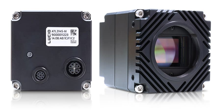
Recognizing these benefits, a number of companies have now introduced both line scan and area array-based cameras based on the 5GBASE-T standard. One example of such an area array camera is LUCID’s Atlas ATL314S 5GBASE-T camera featuring the large format 31.4MP IMX342 CMOS sensor from Sony. With an M12 Ethernet connector capable of transferring up to 25.50 w (PoE+, Type 2) and 5Gbit/s of data, the camera can operate at a resolution of 6464 x 4852 with frame transfer rates of 17 fps at distances of 100m over CAT 6 cable.
Not Just About Speed
There are many reasons why manufacturers of machine vision cameras have embraced the 5GBASE-T standard. Just as Camera Link Extended Full version runs at a maximum of 6.8 Gbits/s over distances of 5m, the USB 3.1 and USB 3.2 interfaces (although they can transfer data at up to 10 Gbits/s and 20 Gbits/s respectively) are limited to camera-to-computer connection distances of 5m (USB 3.1) and 3m (USB 3.2). Similarly, the fastest camera-to-computer interface, CoaXPress (CXP) can transfer data at speeds as high as 12.5 Gbits/s per CXP link, and thus 50 Gbits/s using four links. Cable length is limited to a maximum of 35m at these data rates; however, if using slower data links of 3.125 Gbits/s, cables can be extended to 100m.
Like Camera Link, a relatively expensive (+$2500) PCIe frame grabber is required to implement CXP-based systems. Some high-speed line-scan applications (such as web inspection) demand low latency, low-jitter, point-to-point interfaces, therefore CXP systems must be deployed.
In other, less demanding machine vision applications, 5GBASE-T is a more cost-effective solution (Table 1 below). For ranges of line-scan and area array cameras, vendors offer support for GigE Vision, an interface standard developed in 2006 by a consortium of mainly camera companies and now administered by the Automated Imaging Association (AIA).

Above: With the need for PCIe frame grabbers, CXP and Camera Link systems can offer very low latency and low jitter camera-to-computer connections. However, frame grabbers limit the number of camera connections (CXP max 8 cameras per card, Camera Link max 2 camera per card), increase costs, and reduce system flexibility. The GigE Vision interface allows for versatility when connecting many devices in a system, and has a maximum cable length of 100m.
Side Note
What is a Frame Grabber? A frame grabber is a specialized interface card for Camera Link, CoaXPress, and analog machine vision cameras. Unlike USB or Ethernet cameras, frame grabbers do all the image processing for the camera.
Table 1: Interface Comparison
| Interface | Max Data Transfer Speed | Max Length | Power over Cable | Requires Frame Grabber | Relative System Cost | Features | Cable Required |
|---|---|---|---|---|---|---|---|
| Camera Link | 850 MBytes/s | 10m maximum, 7m (Deca) | Yes (PoCL) | Yes | High | Deterministic, Latency in 4µs |
Shielded twisted pairs, MD-26 connectors |
| CoaXPress | 12.5 Gbit/s Per CXP Link | 100m at 3.125 Gbit/s, 35m (max) at 12.5 Gbit/s |
Yes (PoCXP) | Yes | High | Deterministic Latency (approx 4µs) |
RG59 and RG6 75Coax BNC or DIN 1.2/2.3 connectors (camera) Micro-BNC (frame grabber) |
| USB 3.1 Gen 1 | Up to 5 Gbit/s (after overhead 360 MBps) | 5m | Yes (5V, 2.5W) | No | Low | Average latency 30 μs | USB-type-A and USB-C connectors, USB cable |
| USB 3.2 | Up to 20 Gbit/s | 3m | Yes (5V, 4.5W) | No | Low | Average latency 30 μs | USB-type-A and USB-C connectors, USB cable |
| 10GBase-T | 10 Gbit/s | 55m (CAT 6) 100m (CAT 6A) |
Power over Ethernet+ (PoE+) (IEEE 802.3at) | No | Medium | Average latency 3μs | CAT 7, 6a or CAT 6 cable, optical cabling |
| 5GBase-T | 5 Gbit/s | 100m (CAT 6) | Power over Ethernet (802.3bt) | No | Low | Average latency 3μs | CAT 6, 5e cable |
| 2.5Gbase-T | 2.5 Gbits/s | 100m (CAT 5a) | Power over Ethernet (802.3bt) 4-pair PoE (51W) |
No | Low | Average latency 3μs | CAT 5e cable |
| 1GBase-T | 1Gbit/s | 100m (CAT 5 cable or better) | 13W (after losses) CAT 3/CAT 5 |
No | Low | Latency of 1μs to 12μs | CAT5 Cable |
Embracing GigE Vision and GenICam
GigE Vision provides a framework for transmitting high-speed video and related control data over Ethernet networks, making it easier for developers to build software. As part of the standard, GigE Vision’s GigE Device Discovery Mechanism provides mechanisms to obtain IP addresses and an XML description file that allows access to camera controls and image streams that is based on the GeniCam standard developed by the Verband Deutscher Maschinen- und Anlagenbau (VDMA; Frankfurt am Main, Germany).
While GenICam exposes features of a camera (such as frame rate) through a unified API and GUI, each feature is defined in an abstract manner by its name, interface type, unit of measurement and behaviour. The GenApi module of the GenICam standard defines how to write a camera description file that describes the features of a device, how to be interoperable, and uses the GenICam Standard Features Naming Convention (SFNC) providing a common set of camera features, their names, and their behavior.
The Importance of Being on Time
While GigE Vision and GenICam standards allow for different devices to work with each over Ethernet the issue of deterministic behaviour between devices still needs to be addressed. Business systems and office environments using Ethernet do not require precise or critical timing between devices to function properly, because it is not crucial if all data packets are correctly sent and received, or whether they are sent and received during a known period of time. However, for industrial Ethernet systems such as a machine vision system inspecting parts in a timely fashion, determinism is required. Industrial systems must be highly deterministic because any failure to transmit, receive, or act on processed data at specific times can result in data loss and delays producing an unpredictable industrial system. Determinism is therefore highly important and has been addressed by a number of specialized industrial Ethernet protocols.
Deterministic Ethernet Protocols
Popular industrial Ethernet protocols include PROFINET, EtherNet/IP, EtherCAT, SERCOS III, and POWERLINK. Since there are major differences in the technical approaches taken by each of these protocols, supporting every one of them would be a Herculean software effort for all but the largest manufacturers of industrial automation equipment. Each protocol offers real-time and deterministic behavior for devices and each has various supporting companies and manufacturers. However, EtherCAT is the most adopted and offers both superior performance and market acceptance, delivering real-time, deterministic responses required by industrial machine controllers using low-cost network interface cards (NICs) and Ethernet cables. (2)


To support this collection of protocols, also referred to as a fieldbus, the OPC Unified Architecture (OPC UA – IEC 62451), an open standard developed by the OPC Foundation, can be used to specify the information exchange for industrial communication on computer-based machines, in-between machines, and from machines to and from computers systems.

With OPC UA, developers can take advantage of OPC’s data model and services that enable devices to exchange data with an agreed and shared meaning, rather than mapping data as byte streams. At the same time, the EtherCAT Technology Group (ETG, Nuremberg, Germany) and the OPC Foundation’s technologies complement each other with EtherCAT being used as a real-time-Ethernet fieldbus for machine and plant controls and OPC UA as a platform for scalable communication.
Side Note
Association Memberships

VDMA has over 3200 corporate members
![]()
OPC has over 700 corporate members
Making Machine Vision Systems
While the collaborations above are useful, they do not specifically address the needs of developers of machine vision systems wishing to leverage Ethernet-based systems on the factory floor. To do so, the VDMA has collaborated with the OPC Foundation to form an OPC Vision Initiative to develop an OPC UA companion specification for machine vision (see “OPC UA Vision,VDMA Specification”, Draft Version November 2018).
While the OPC UA describes data, functions, and services of embedded devices, machines and data transport for data modelling, OPC Vision allows industry-specific definitions of products such as cameras to be defined, similar to the GenICam Standard’s Features Naming Convention. As well, the OPC Vision Interface can be integrated with fieldbus standards such as EtherCAT to form a complete system model for real-time deterministic systems that can be integrated with OT production control and IT systems.

With the emergence of the OPC Unified Architecture (OPC UA), the OPC Vision Initiative and the IEEE 802.1, standards for time-sensitive networking (TSN) companies can use a single Ethernet network for both time-critical, deterministic applications such as image capture and less time-critical IT systems. Since the OPC UA TSN standard can be applied to computer-based nodes on the network, including cameras, PCs, PLCs, and server-based systems, it will be especially useful in developing edge-based and cloud-based network applications.
5GBASE-T: The Sweet Spot
5GBASE-T cameras coupled with standard Cat 6 cables allows cameras to be easily located at up to 100m from the host computer in a variety of flexible network topologies. Eliminating the need for relatively expensive frame grabbers also lowers the overall system cost while still allowing 5Gbits/s image data transfer from the camera, fast enough to address a broad range of vision applications. When established, efforts such as the OPC Unified Architecture (OPC UA) and the OPC Vision Initiative will ease the deployment of 5GBASE-T cameras in industrial fieldbus-based Ethernet networks, simplifying the task of systems integration. These aspects combine to build a balanced interface offering flexibility, bandwidth, low cost, and strong reliability for high speed vision systems.
(1) “NBASE-T Technology Overview” by NBASE-T Alliance https://youtu.be/cLfuhrBaza8
(2) “Five Real-Time, Ethernet-Based Fieldbuses Compared,” a White Paper prepared by Kingstar (Waltham, MA, USA)