


 Support Center
TCP vs. UDP
Table of Contents
UDP is the chosen protocol for the GigE Vision standard and is used by all GigE Vision based Ethernet cameras. UPD offers excellent streaming performance, low latency, multicast, and an overall simpler design than TCP. UDP is a connectionless protocol that does not require a handshake between sending and receiving devices before data transmission begins. It offers a more “hands-off” approach to data sending as there is no flow control or packet reliability built into it. On the other hand, TCP is a connection-oriented protocol that must establish a client-to-host connection. It also has built-in reliability features such as for flow control, packet retransmission, and packet coalescing. In general, UDP was designed to focus on speed and simplicity, without the extra features of TCP, while TCP was more focused on transmission reliability.
TCP and UDP at a Glance
| TCP | UDP | |
|---|---|---|
| Connection Design | Connection-oriented | Connectionless |
| Connection Handshake | Yes (SYN, SYN-ACK, ACK) | None. PC sends discovery packets to cameras on same subnet |
| Guaranteed Frame delivery | Yes | No |
| Transmission Method | Stream-oriented | Datagram |
| Data Retransmission | Yes (hardware layer) | Optional (requires filter driver) |
| Flow Control | Yes (hardware layer) | Optional - Inter-packet delay |
| Jumbo Frames | Yes | Yes |
| Receive Side Coalescing / Large Packet Coalescing | Yes | No |
| Multi-cast | No | Yes |
Why Use UDP for the GigE Vision standard?
When GigE Vision was established (2006), camera vendors chose UDP not only for it its efficient streaming performance, but also for its simplicity. UDP could be quickly implemented into the standard and missing reliability features could be added on top of UDP, with those features running at the application level (running in software, utilizing CPU resources on the host PC and the camera’s firmware). These reliability features would also be optional for camera vendors making it even simpler if vendors choose to forgo these features. The GigE Vision standard enables Ethernet devices to communicate using UDP by defining device control, stream, discovery, and feature list mechanisms:
- The GigE Vision Control Protocol (GVCP) defines how GigE Vision applications can configure and establish control over devices.
- The GigE Vision Stream Protocol (GVSP) specifies the different data types and transmission methods used to transfer images from a camera to a PC including an optional packet retransmission feature.
- The GigE Device Discovery Mechanism defines how devices are found on a network.
- An XML file contains the GenAPI description that defines all camera functions. This description is based on the GenICam standard.
In comparison, TCP is a more complicated protocol to implement on the camera, requiring more hardware resources on the camera (larger FPGA room, more on-board memory) as mandatory features, such as packet retransmission, must be implemented on the hardware level. Choosing UDP for GigE Vision ultimately allowed camera vendors flexibility in their Ethernet camera development.
Even though UDP was chosen, camera manufacturers and customers understood that data transfer reliability could not be completely ignored. The GigE Vision standard includes sections on reliability features similar to TCP with these optional features being added to the header of each data packet. The GigE Vision standard includes a GVSP header with sequence information allowing packets of a frame to be sent out-of-order and realigned after delivery. The GVSP header also facilitates packet retransmission if packet is dropped.

Challenges of UDP for 10GigE Cameras
The current implementation of UDP for GigE Vision was used with 1GigE bandwidth in mind. As mentioned earlier, reliability features missing from UDP are built into the GigE Vision standard on the application layer, meaning any reliability feature that is used will be limited by the amount of available CPU resources on the host, quality of the camera’s software and filter driver, and how robust the camera’s firmware is at handling extra features. For example, for many camera manufacturers, packet retransmission in GigE Vision requires a specialized software driver on the host PC, called a filter driver, to monitor for any missing packets. When a missing packet is noticed by the PC, it sends a retransmission request to the camera. The camera then needs to parse the packet, which usually takes place in the camera’s firmware, and then fetch that packet from the camera’s image buffer. The camera will have to pause normal transmission and retransmit the requested packet. If there are several missing packets, interspersed throughout the frame, this can burden both the PC and camera. However, at 1 Gigabit speeds, CPU and camera resources needed to monitor and resend dropped packets are readily available.
Example of the host PC dealing with out-of-order packets and dropped packets. Data delivery is monitored by the Filter Driver supplied by the camera manufacturer because UDP doesn’t offer any built-in reliability features. This driver reads the GVSP header on each packet.
LUCID has continuously worked to optimize the UDP data transfer under GigE Vision. Our filter driver provides fast, low latency, and optimized CPU performance, along with all the optional reliability features available to users. For the most efficient performance, installing LUCID’s filter driver (LUCIDLwf.sys) provides fast packet monitoring with DMA packet transfers. For example, streaming four Atlas10 10GigE cameras simultaneously at full bandwidth results in only an average of 8% CPU resources.
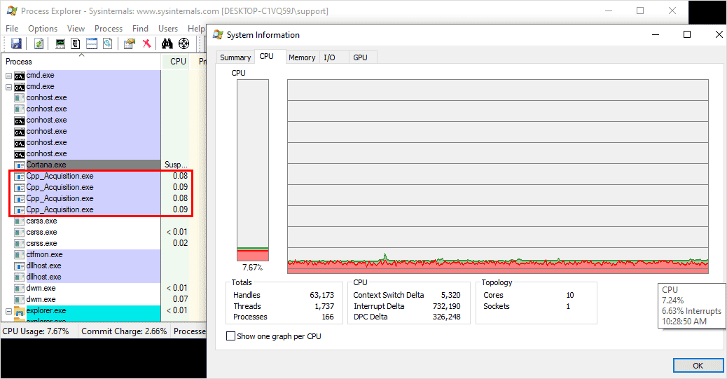
Run multi-10GigE Atlas10 cameras with optimized CPU resources with LUCID’s UDP filter driver. See PC specs here.
But for some 10GigE applications, especially those applications where triggering for full frame delivery is absolutely critical, the GigE Vision UDP technology can reach its limits. The enormous increase in data streamed at 10GigE can cause reliability issues, especially on multi-camera 10GigE applications with less than ideal host PC specifications (See our KB article “Sample PC Config for Streaming Multiple Atlas10 Cameras“). With 10 times more data to monitor per camera, the host PC and the camera can begin to struggle after an initial issue causes a packet retransmission, forcing packets to be dropped when the CPU is too busy to handle the data stream. This will lead to corrupt or partial images. As the bandwidth of image transmission grows the chance of dropping more packets grows, creating a vicious cycle as the CPU utilization continues to increase as it continues request packet resends from the camera. While the GigE Vision standard added reliability features on top of UDP, the current use of UDP and packet retransmission can cause a domino effect in corrupt images due to maxed out CPU resources.
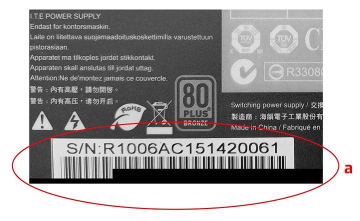
Examples of corrupted images under UDP transmission. Black bars typically occur during the start of a stream as the image buffers have yet to be used (a). A scene in motion suffering from dropped packets will show a previous image as those are the last packets held in image buffer (b).
TCP Reliability: Starts with a Handshake
Compared to UDP, TCP has built in reliability features and allows Ethernet cameras, including 10GigE cameras, to guarantee full frame delivery. Note that this does not guarantee every frame being delivered, it means that all packets for a frame (image) will be delivered. In other words, an application will not encounter corrupted or partial images (examples shown above), but it can still encounter dropped frames if there are critical failures with the connection or on the host PC.
Full frame delivery is important for applications that require camera triggering for inspection. In these situations, it is imperative that no packets are dropped which could result in corrupt images, leading to issues such as OCR misreading or poor object detection. Unlike UDP, TCP does not need a filter driver installed on the host PC and manages packet retransmission along with additional reliability features at the hardware level, utilizing the network interface card (NIC) and the camera’s FPGA. The foundation of a reliable data transmission begins with TCP’s three-way handshake. This handshake creates a TCP socket connection, reserves system resources and sets the TCP window size (buffer) for data transmission. Because it reserves system resources, it must also be terminated before those resources can be used for other tasks.

Unlike GVSP using UDP, where GVSP headers are inserted into all data packets for a frame, GVSP using TCP only inserts the GVSP header once per frame. This reduces overhead.
The TCP handshake (SYN, SYN-ACK, ACK) with the Atlas10 10GigE camera establishes a TCP socket connection, reserves system resources, and sets the TCP window size (buffer) for data transmission.
Once a TCP connection is established between the camera and host PC, the application can now take advantage of more reliable packet delivery, higher frame rates, and consistently low CPU utilization. These three advantages are achieved through the following TCP features:
- TCP Flow Control and Windowing (Hardware Level)
- Packet Retransmission (Hardware Level)
- Large Receive Offload (Linux) & Receive Side Coalescing (Windows) (Both hardware level)
TCP Flow Control and Windowing
TCP Flow Control
Using TCP, the NIC must send an acknowledgement packet (ACK) back to the camera to confirm it has successfully received a specific amount of data (in bytes). The ACK packet tells the camera how much data has been received, how much data is on the line (in transit), and how much room is left in the “sliding window”. ACKs help set the frame rate on the camera by forcing the camera to pause and reduce the frame rate until the correct ACKs are received. This is called Flow Control and increases packet delivery reliability by storing any accumulating packets into the TCP sliding window and camera’s image buffer until the NIC is ready. This allows the camera and host PC to continually monitor the connection quality at the hardware level. While the NIC is set to try its best to send an ACK for each packet received, it could delay and send one ACK for multiple packets depending on how busy the host PC is. The sending of ACKs also doesn’t increase overhead or take up bandwidth on the camera’s end because 10GigE is full duplex.
Camera Flow Control
On the camera, each frame (image) requests an ACK from the host PC before the next frame can begin off-loading into the TCP Sliding Window. If the host PC is busy for too long, the 880MB of Atlas10 on-camera frame buffer will fill up with frames and eventually the camera will drop frames. This will result in a lower frame rate reducing the flow of data until the PC is ready. However, partial images with missing data will never be sent to the host PC. This is because the last frame in the camera’s frame buffer will be held until the camera has sent all the frame’s packets and the host PC has sent the appropriate number of ACKs back to the camera. TCP ACKs are never seen by the camera’s firmware as they are processed in the camera’s FPGA and the host PC’s NIC. Note that LUCID sets the TCP ACK frequency to 1 as this gives the lowest latency (this setting is available in Windows only).
TCP Packet Retransmission
TCP packet retransmission works in conjunction with TCP Flow Control as it utilizes the ACKs to make sure that packets are being received. In the case of a missing packet on the host PC, the host will send three ACKs with the same acknowledgement number to initiate a packet retransmit. The camera will also automatically resend the last packet if it doesn’t receive an ACK when the “Retransmission Timer” expires. The host can request any data that is in the TCP Window. Because packet retransmission is managed by the TCP hardware, there is no longer a need to set a bandwidth reserve (DeviceLinkThroughputReserve) for GigE Vision packet retransmission. This will free up roughly 10% bandwidth (LUCID’s default setting when using UDP) and allows the camera to reach higher frame rates* (*dependent on the sensor’s maximum frame rate). While TCP still needs to use up bandwidth for packet retransmission, the bandwidth amount is dynamically adjusted by the TCP hardware without the need for the user to set a static amount.
Large Receive Offload (LRO) / Receive Side Coalescing (RSC)
Large Receive Offload (RCO, Linux) and Receive Side Coalescing (RSC, Windows) allows the NIC to combine smaller packets into larger segments, reducing the number of smaller packets needed to be processed by the CPU. When the NIC receives the packets, they are first checked to see if they can be combined (correct sequence, valid CRC, proper TCP flags). If they can, the header for the initial packet is kept but the headers for the following packets are removed. This continues for all incoming packets up until the interrupt (interrupt moderation). Packet coalescing does not add extra latency because the NIC coalesces packets within the interrupt moderation time. Fewer but larger segments produce a more efficient stream. The concept is similar to enabling jumbo frames and interrupt moderation, both of which help to reduce CPU utilization. (See Tips for reaching maximum frame rate). Packet coalescing is not possible using UDP because UDP has defined beginning and ends to each packet. But because TCP is stream-based, there are no defined boundaries to the data.
LRO and RSC results in lower CPU utilization, especially on 10GigE multi-camera applications. This helps free up CPU resources allowing the CPU to focus on other vision tasks such as object detection or classification.
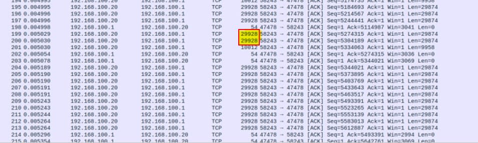
Above: The Atlas10 camera and NIC are set to 16k jumbo frames but they are being combined by the NIC into 30k (29928) frames, thanks to Large Receive Offload in Linux. This reduces the number of packet segments that the system needs to process. Packet coalescing is only possible with TCP thanks to it being stream-based.

Above: Four Atlas10 cameras streaming at 10GigE in Ubuntu 18.04. ~2.2% CPU utilization during image acquisition without LRO.

Above: Four Atlas10 cameras streaming at 10GigE in Ubuntu 18.04. ~1.9% CPU utilization during image acquisition with LRO enabled.
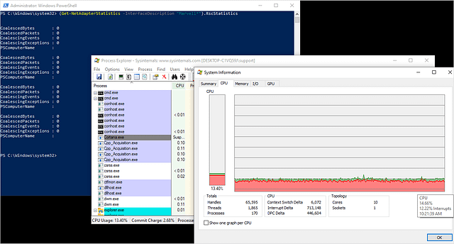
Above: Four Atlas10 cameras streaming at 10GigE in Windows10. ~13% CPU utilization during image acquisition without RSC.

Above: Four Atlas10 cameras streaming at 10GigE in Windows10. ~11% CPU utilization during image acquisition with RSC enabled. (See PC specs here.)
Conclusion
LUCID now supports both UDP (GigE Vision) and TCP protocols for our Atlas10 10GigE cameras. Users can switch between protocols easily using our Arena Software Development Kit. While LUCID’s filter driver greatly optimizes UDP for fast, low latency data transmission, some users may wish to prioritize guaranteed full frame delivery above all else by choosing TCP. If under a UDP connection an application is suffering from dropped packets or high CPU usage, TCP can provide data transmission that’s more reliable between 10GigE cameras and the host PC. TCP’s flow control, packet retransmission, and LRO/RSC technologies provides high bandwidth image transfers that guarantee full frame delivery, all while operating at the hardware level. Thanks to LUCID’s proprietary 10GigE IP core on the Atlas10 cameras, LUCID now supports TCP connections along with traditional UDP, giving users more choice in building a reliable 10GigE vision application.
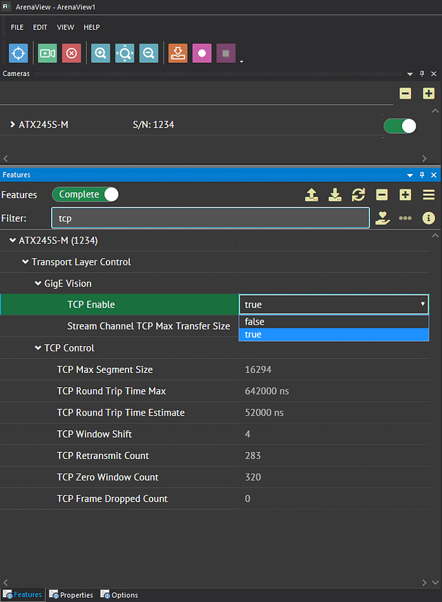
Changing from UDP to TCP is easy in ArenaView. Just stop acquisition, change your protocol, and start again.