Support Center
Getting Started
Welcome! Is this your first time setting up a LUCID camera? If so, this page is the perfect place to get started. Here you will find all the necessary steps needed to set up your camera.
General considerations
Check the manufacturer’s documentation for instructions on how to install your network interface card.
Unless otherwise instructed to do so, disconnect the power supply from the computer before installing or removing a NIC from a host computer.
Note that LUCID offers network interface cards (NICs) on our webstore.
RDMA NICs purchased from LUCID
If you have purchased an RDMA NIC from LUCID, follow the instructions for Windows or Linux.

Remove Dust Cap
Press the dust cap button to release the cap from the camera.

Attach Tripod Adapter
Use three M2 screws (2 in the front and 1 in the back) to attach the tripod adapter to the camera.
Use a standard 1/4″-20 mounting screw with the tripod adapter. Using a nonstandard mounting screw longer than 5.5 mm on the adapter may damage the camera.

Attach a Lens
Screw in an appropriate lens into the camera’s lens mount.

Connect Cable to Network or PC
Connect a Cat 5e/6/6a cable to (a) PoE switch, (b) PoE injector or (c) PoE network interface card.
Note: You must use at least a Cat 5e cable to utilize GigE bandwidth.

Connect Cable to Camera
Connect a Cat 5e/6/6a cable to the camera. The camera will briefly blink red upon power-up and then start blinking green once it is ready to stream.

Remove Dust Cap
Press the dust cap button to release the cap from the camera.

Attach Tripod Adapter
Use four M2 screws to attach the tripod adapter to the camera.
Use a standard 1/4″-20 mounting screw with the tripod adapter. Using a nonstandard mounting screw longer than 5.5 mm on the adapter may damage the camera.

Attach a Lens
Screw in an appropriate lens into the camera’s lens mount.
OPTIONAL: Attach an IP67 Lens Tube

Step 1: Screw on the lens tube ring that comes with the LUCID lens tube accessory. Turn the ring until there is contact with the front base of the camera (b). The C-mount should also extent passed the ring by a small amount, approx. 0.3mm (a).

Step 2: Screw on the lens and then screw on the lens tube. Make sure that there is no gap between the back of the lens tube and the back flap of the ring.
Connect Cable to Network or PC
Connect a Cat 5e/6/6a cable to (a) PoE switch, (b) PoE injector or (c) PoE network interface card.
Note: You must use at least a Cat 5e cable to utilize GigE bandwidth.

Align Indent Key of M12 Port and Cable Pins
The camera’s M12 Ethernet port and M12 X-Coded cable have a specific indentation to correctly align the cable pins to the port pin holes. You must align them together first. Do not force the connection.

Connect Cable to Camera
Screw in the M12 X-Coded Cat 5e/6/6a cable to the camera. The camera will briefly blink red upon power-up and then start blinking green once it is ready to stream.

Remove Dust Cap
Press the dust cap buttons to release the cap from the camera.

Attach Tripod Adapter
Use four M4 screws to attach the tripod adapter to the camera.
Use a standard 1/4″-20 mounting screw with the tripod adapter. Using a nonstandard mounting screw longer than 5.5 mm on the adapter may damage the camera.

Attach a Lens
Screw in an appropriate lens into the camera’s lens mount.
OPTIONAL: Attach an F-Mount Lens to TFL-Mount Adapter (PN: ADA-TFL-F)

For customers who wish to use F-Mount lens with the Atlas please first attach the the “F-Mount Lens to TFL-Mount Adapter” to the Atlas camera.
Connect Cable to Network or PC
Connect a Cat 5e/6/6a cable to (a) NBASE-T PoE switch, (b) PoE injector or (c) NBASE-T PoE network interface card. Note: You must use at least a Cat 5e cable and NBASE-T switch or interface card to utilize 5GBASE-T (5GigE) bandwidth.

Align Indent Key of M12 Port and Cable Pins
The camera’s M12 Ethernet port and M12 X-Coded cable have a specific indentation to correctly align the cable pins to the port pin holes. You must align them together first. Do not force the connection.

Connect Cable to Camera
Connect the M12 X-Coded side of your Cat 5e/6/6a cable to the camera. The camera will briefly blink red upon power-up and then start blinking green once it is ready to stream.

Attach Tripod Adapter
Use four M4 screws to attach the tripod adapter to the camera.
Use a standard 1/4″-20 mounting screw with the tripod adapter. Using a nonstandard mounting screw longer than 5.5 mm on the adapter may damage the camera.

Connect Cable to Network or PC
Connect a Cat 5e/6/6a cable to (a) Ethernet switch, (b) network interface card.
Note: You must use at least a Cat 5e cable to utilize GigE bandwidth.

Align Indent Key of M12 Port and Cable Pins
The camera’s M12 Ethernet port and M12 X-Coded cable have a specific indentation to correctly align the cable pins to the port pin holes. You must align them together first. Do not force the connection.

Connect Cable to Camera
Connect the M12 X-Coded side of your Cat 5e/6/6a cable to the camera.

Connect M8 Power Supply Cable to the Camera
Connect the power supply to an outlet and then to the M8 port on the Helios. The camera will briefly blink red upon power-up and then start blinking green once it is ready to stream.
Arena SDK
To access cameras features you will need to download the Arena Software Development Kit (SDK) here. The SDK is compatible with all LUCID cameras – this includes polarization camera models and Helios ToF models. Depending on which camera is being used certain Arena functions may or may not be enabled. The Arena SDK also includes all the tools needed to develop your own custom vision application.
After installing Arena SDK, visit our Getting Started with ArenaView in Windows guide for more details on using the SDK and our ArenaView GUI.
The Arena SDK includes:
- Arena C++, C, and .NET Library
- ArenaView GUI (Quickly visualize image streams from mono/color, polarization, and 3D ToF camera models)
- IP Configuration Utility
- Lightweight Filter (LWF) Driver Installer
- Arena HTML Help Documentation
3rd Party Software Guides
If you application uses 3rd party software packages we have helpful getting started guides for popular industry software packages. Please visit our 3rd Party Software Getting Started Guides page for step-by-step instructions.
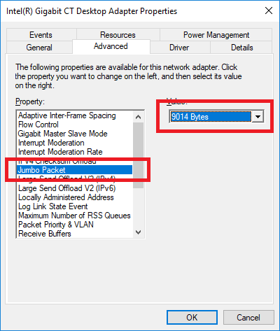
Lucid Vision Labs recommends enabling jumbo frames on your Ethernet adapter. A jumbo frame is an Ethernet frame that is larger than 1500 bytes. Most Ethernet adapters support jumbo frames, however it is usually turned off by default.
Enabling jumbo frames on the Ethernet adapter allows a packet size of up to 9000 bytes to be set on the camera. The larger packet size will enable optimal performance on high-bandwidth cameras, and it usually reduces CPU load on the host system. Please note in order to set a 9000 byte packet size on the camera, the Ethernet adapter must support a jumbo frame size of 9000 bytes or higher. Jumbo frames can be enabled in your Ethernet adapter’s properties.
If you still experience issues such as lost packets or dropped frames, you can also try:
- Updating the Ethernet adapter driver (you may need to enable jumbo frames again after updating).
- Increasing the receive buffer size in your Ethernet adapter properties.
- Reducing the DeviceLinkThroughputLimit value (this may reduce maximum frame rate).
For the majority of the time the easiest way to identify your camera IP address is through our ArenaView GUI. This information is displayed under the Start Page. If you are having difficulty identifying the IP address or would like to edit IP settings please read below for addition camera IP information.
Camera IP Setup
Persistent IP and DHCP configurations can be disabled on the camera. The default camera configuration is as follows:
| Persistent IP | Disabled |
| DHCP | Enabled |
| LLA | Enabled (always enabled) |
Out of the box, the camera first attempts to connect using DHCP. If the camera is unable to connect using DHCP, it will use Link-Local Addressing.
Setting Up Persistent IP or DHCP on the Camera with IP Config Utility
Arena SDK provides a simple command-line utility named IP Config Utility to configure your camera’s IP address.
The following command shows all connected cameras:
> IpConfigUtility /list

[index] MAC             IP              SUBNET          GATEWAY                 IP CONFIG
[0]     1C0FAF000001    169.254.101.0   255.255.0.0     0.0.0.0                 DHCP= 1 Persistent Ip= 1 LLA = 1
The following commands show how to enable and set a persistent IP address on a camera with the MAC address of 1C:0F:AF:00:00:01:
> IpConfigUtility /persist -m 1C0FAF000001 -p true -a 192.168.0.10 -s 255.255.0.0 -g 0.0.0.0
> IpConfigUtility /config -m 1C0FAF000001 -p true
The following commands show how to enable persistent IP and set a persistent IP address on a camera listed at index 0:
> IpConfigUtility /persist -i 0 -p true -a 192.168.0.10 -s 255.255.0.0 -g 0.0.0.0
> IpConfigUtility /config -i 0 -p true
The following command shows how to enable DHCP on a camera listed at index 0:
> IpConfigUtility /config -i 0 -d true
The following commands show how to enable persistent IP and DHCP and set a persistent IP address on a camera listed at index 0:
> IpConfigUtility /persist -i 0 -p true -a 192.168.0.10 -s 255.255.0.0 -g 0.0.0.0
> IpConfigUtility /config -i 0 -p true -d true
Forcing an IP Address on the Camera with IP Config Utility
The following command shows how to force an IP address on a camera with the MAC address of 1C:0F:AF:00:00:01:
> IpConfigUtility /force -m 1C0FAF000001 -a 192.168.0.10 -s 255.255.0.0 -g 0.0.0.0
Setting Up LLA on the Ethernet Adapter
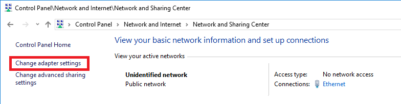
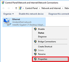
The following steps illustrate an example configuration for one Ethernet adapter to use the LLA space.
-
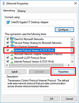
Navigate to Control Panel -> Network and Internet -> Network and Sharing Center
-
Click Change adapter settings
-
Right-click on your Ethernet adapter and click Properties
-
Select Internet Protocol Version 4 (TCP/IPv4) and click Properties
-
Select Use the following IP address and enter the following details:
IP address 169.254.0.1 Subnet mask 255.255.0.0 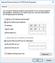
Default gateway and DNS server details can be left blank.
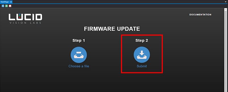
Updating your camera’s firmware is easy with our ArenaView GUI and fwa file. The firmware fwa files are located in the camera model webpage under the “downloads” tab. Before beginning the update process please connect your camera to your host computer and install our Arena SDK. The following steps explain how to update your camera firmware using ArenaView GUI which can be accessed through the Windows Start Menu under Lucid Vision Labs folder -> ArenaView (or C:\ProgramData\Lucid Vision Labs\ArenaView\ArenaView.exe)
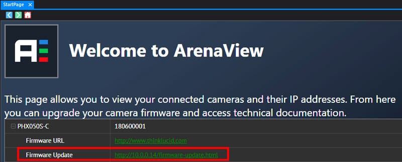
- Open the ArenaView Start Page. This page opens at program startup. It is also available by clicking View -> Start Page.
- Click the [+] next to the camera you would like to update on the Start Page and click on the Firmware Update link.
- Click Choose a file on the Firmware Update page and select your fwa file.
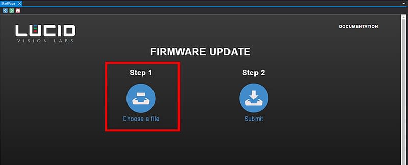
- Click Submit on the Firmware Update page. This will start the firmware update process.
Firmware Update Process
The Firmware Update page will show the progress of the update. During the update, the camera will not be accessible for control or image capture. The update may take a few minutes to complete. Please refrain from removing power from the camera during the update.
When the firmware update is complete, the camera will reboot. Once the update is finished, you can close the Firmware Update page and access the camera again.
The above information is just a subset of information taken from the full Arena SDK help documentation. This information is meant to get you imaging as quickly as possible. For more detailed setup instructions please refer to the full Arena SDK documentation. Within the documentation, there is a “Getting Started with ArenaView in Windows“ page which describes additional information that might be beneficial to camera setup.
The default folder the Arena SDK help documentation is installed to is C:\Program Files\Lucid Vision Labs\Arena SDK\docs\html. The starting page is index.html, and we install a Start Menu shortcut called “Arena SDK Documentation” for easy access to this page. You can also access the documentation from the ArenaView StartPage, which is a tab that opens automatically when ArenaView starts.”
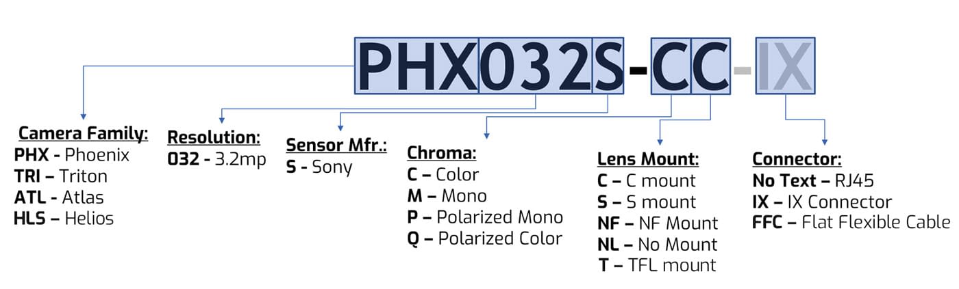
Additional Info: What do our camera model numbers mean?