 Support Center
Using GPIO on LUCID Cameras
Introduction
Many high precision applications using machine vision cameras require the camera to capture a frame at a precision instant (ie. When the target object moves into camera’s field of view) or multiple cameras to capture frames synchronously. This application note outlines the method available to trigger the camera to capture a single frame, a series of frames or synchronize multiple LUCID cameras to capture image or sequence of images together precisely for these applications.
The camera has three operation modes – Free-run or Stream Mode, single frame or Snapshot Mode and Trigger Mode.
The setup is simple for all 3 modes. The following section describes how to set LUCID camera(s) in Free-run Mode, Snapshot Mode and Trigger Mode.
Prerequisites
- 1x LUCID Phoenix or 1x Triton Camera
- One GPIO cable for Phoenix or Triton
- Arena Software
Free-Run Mode
In Free-run mode, the camera with the build in sensor produces a stream of images at a predefined acquisition frame rate continuously. The sensor captures one frame of image into the pixel array and transfers the pixel data over the sensor interface into the camera electronics. During this transfer, the sensor may capture the next frame of image. Under this mode, the exposure of the current frame may overlap with the readout of the previous frame.
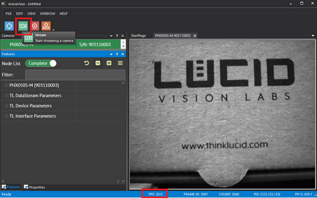
To put camera in Free-run mode, simply:
- Connect the camera
- Launch Arena
- Click Stream button.
In the above example, the camera free-runs at a fixed 20 frame per second without any external control over when exactly each frame is captured.
Snapshot Mode
Compared to Free-run mode, Snapshot mode takes only one image. The software grabs one frame out of the Free-run stream and pass it to the application level. This mode is useful when the user only wants to capture one image at any time.
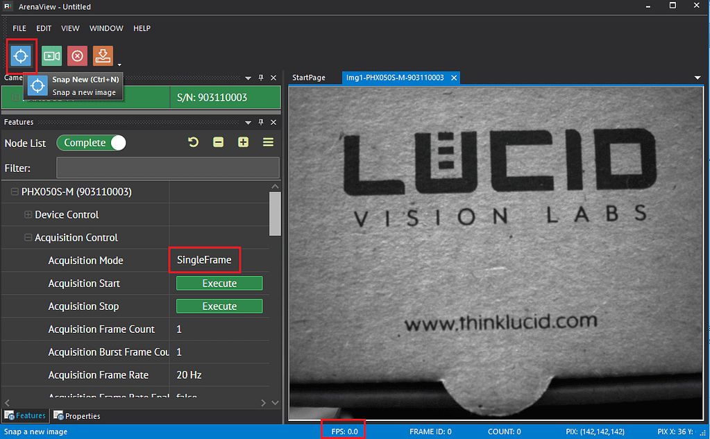
To capture a single frame from the camera in Snapshot mode, simply:
- Connect the camera
- Launch Arena
- Click Snap button
The software puts the camera in SingleFrame Acquisition Mode, snaps an image (AcquisitionStart cmd) and then pass that frame to the application for display. The framerate is undefined (shown as 0.0) as only one image was captured.
Trigger Mode
In an industrial environment, many applications need to capture an image at a given point in time. The use case could be object inspection, when the target object moves to the front of the camera, the application would need to take an image of the object at that precise moment. The host machine is often equipped with ability to output an electrical signal exactly when the object is passing in front of the lens of the camera.
This electrical signal generated by a device such as a photodetector is the key driver for the camera to start capture. When the camera is operating under this mode, it is said to be in trigger mode.
Note: When a rolling shutter sensor is triggered, the sensor needs to take and read out an extra frame to reset the sensor. This typically reduces the maximum achievable trigger frequency to about half of the maximum value of the AcquisitionFrameRate node on most rolling shutter cameras.
Cable and Connector Information
Power
We recommend to power LUCID cameras either via the camera’s Ethernet connector (PoE) or via the camera’s I/O connector.
- When using PoE, the power supply must comply with the IEEE 802.3af standard. You can find recommended parts to power the camera in LUCID web store.
- When powering via the GPIO, please use pin VAUX(12-24V DC Power Input)
GPIO Connector
LUCID recommends using LUCID’s standard GPIO-8P20 and GPIO-M8 for Phoenix and Triton cameras’ I/O control.
Phoenix GPIO Connector Information
| Manufacturer | JST |
| Part Number Receptacle (camera) | JST BM08B-NSHSS-TBT(LF)(SN) |
| Part Number (cable plug) | JST NSHR-08V-S |
| LUCID Part Number | GPIO-8P20 |
| Number of pins / wires | 8 |
| Wire Gauge | AWG 28 |
| Length of the Wires | 20 cm |
| Mechanical Connection | Latch lock |
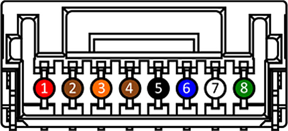
The pin out of the Phoenix GPIO receptacle and color mapping of the wires is as the following:
Triton & Atlas GPIO Connector Information
| Manufacturer | Phoenix Contact |
| Part Number Receptacle (camera) | SACC-CI-M8FS-8P SMD R32 – 1412247 |
| LUCID Part Number | GPIO-M8 |
| Number of pins / wires | 8 |
| Wire Gauge | AWG 26 |
| Length of the Wires | 1m |
| Mechanical Connection | M8 Screw-locking |
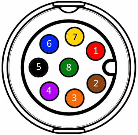
The pin out of the Triton and Atlas GPIO receptacle and color mapping of the wires is as the following:
GPIO Pin Mapping and Function
The camera uses the following functionality on each pin:
| Pin Number | Phoenix Color | Triton/Atlas Color | Pin Description | Line Selector |
|---|---|---|---|---|
| 1 | Red | Red | VAUX (12-24V DC Power Input) | – |
| 2 | Brown | Brown | Non-isolated bi-directional GPIO channel | Line 2 |
| 3 | Orange | Orange | VDD GPIO (2.5V Power Output) | Line 4 |
| 4 | Brown | Purple | Non-isolated bi-directional GPIO channel | Line 3 |
| 5 | Black | Black | GND (Camera GND) | – |
| 6 | Blue | Blue | OPTO GND (Opto-isolated Reference) | – |
| 7 | White | Yellow | OPTO OUT (Opto-isolated Output) | Line 1 |
| 8 | Green | Green | OPTO IN (Opto-isolated Input) | Line 0 |
Trigger Configuration
To set up the camera in trigger mode:
- Connect camera to the host PC
- Launch Arena
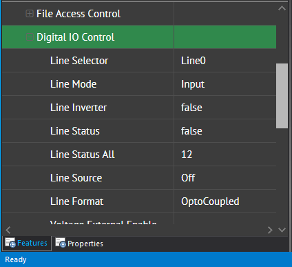
3. Select the camera and navigate to the “Digital IO Control” section.
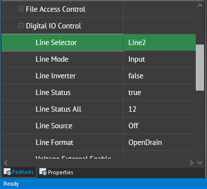
4. Select the Line you wish to configure to take as trigger input. In the example below, Line2 (brown) is configured as trigger.
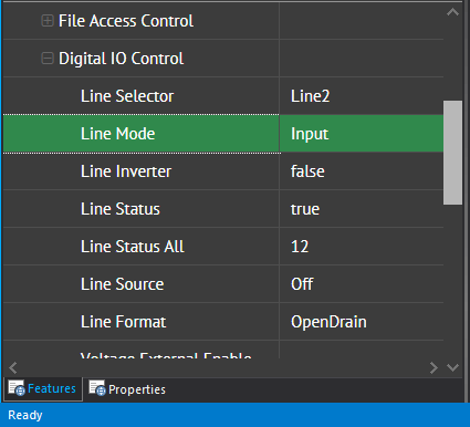
5. To configure line2 as trigger input, set Line mode to Input.
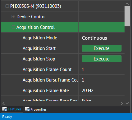
6. Now the camera’s GPIO is set up to take trigger input; however, the camera is not yet in Trigger Mode. To do so, navigate to “Acquisition Control”.
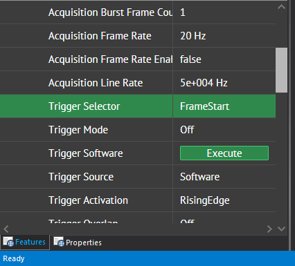
7. For the trigger signal to prompt for a signal frame acquisition, set Trigger Selector to FrameStart.
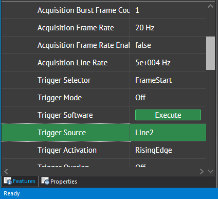
8. Set Trigger Source to Line2 – the line we configured in step 5.
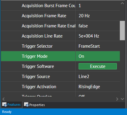
9. Turn Trigger Mode on.
10. Click stream button and you should now see one image per trigger signal going into the GPIO brown pin.
Over Trigger
If the input trigger frequency is greater than the sensor framerate, the trigger is discarded, not delayed.
All shorter signals like spikes are ignored:
Multi-frame Trigger
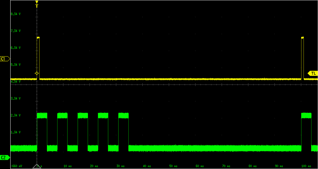
To capture multiple images per trigger pulse, please stop the camera from acquisition and put it in the Burst mode:
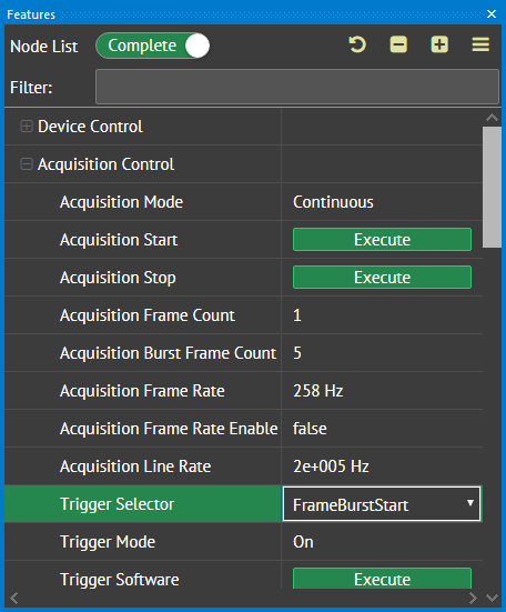
- Set Trigger Selector to FrameBurstStart.
- Configure Acquisition Burst Frame Count to the number of frames you wish to capture per trigger pulse (in this example is it set to 5).
Now you will see 5 strobe pulses indicating 5 frames captured for each corresponding trigger input.
Setting Up Strobe Output
In certain applications, other devices need to be synchronized with camera capture regardless of the camera’s operation mode (Freerun or Trigger). In this case, the user can take advantage of the strobe output function on the camera to know when exactly a frame capture is taking place. In the following section, strobe configuration is discussed.
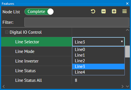
1. Select a line to output strobe signal in the Line Selector row, in this example Line 3 is used.
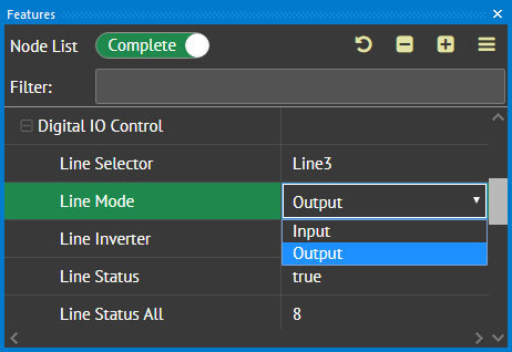
2. Set Line Mode to Output.
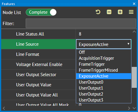
3. To output strobe signal matching the camera exposure. Set Line Source to ExposureActive.
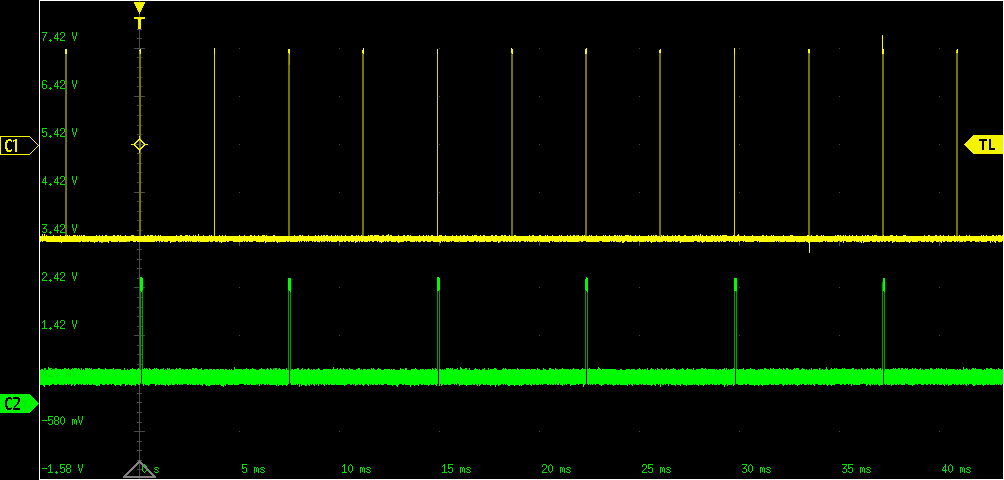
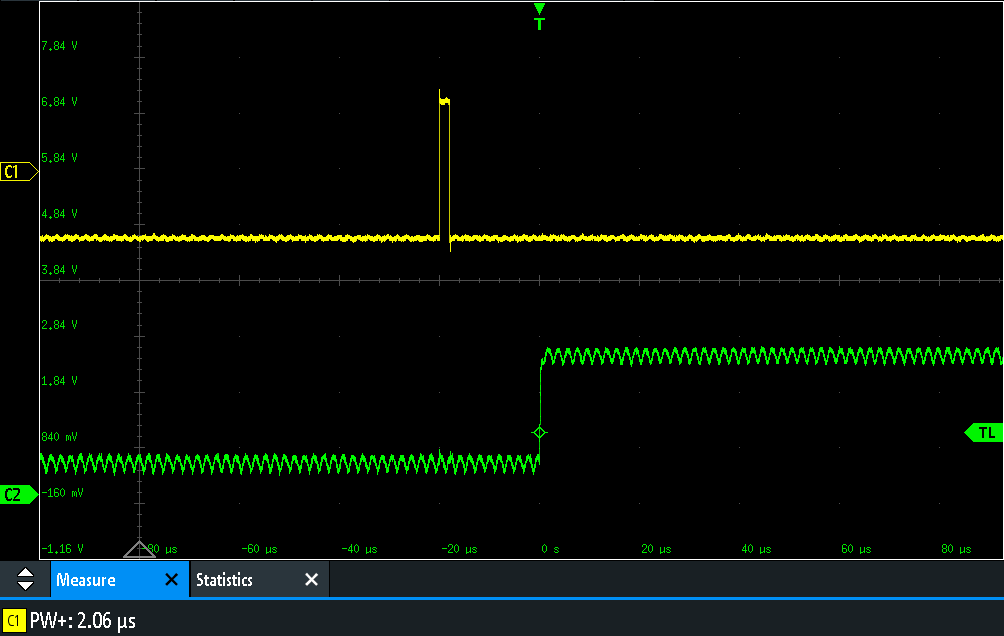
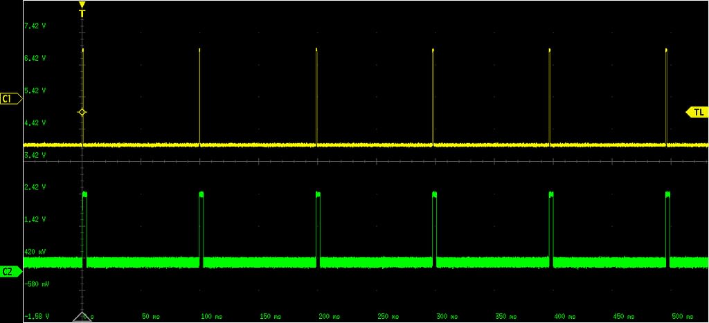
4. Click Stream button in Arena, if the camera is in free-run mode you will see continuous signal corresponding to each exposure. If the camera is in trigger mode and Stream is clicked, the following patter can be observed on the scope. The yellow signal is the trigger in to the camera, the green one is the strobe output. The Image capture is synchronous to the rising edge of the trigger pulse.
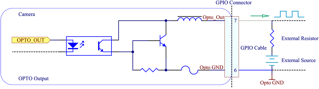
Opto-isolated Strobe Output
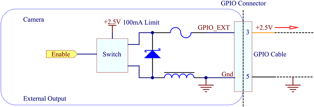
LUCID cameras are equipped with opto-isolated output pins. The following diagram shows a typical circuit you can use to monitor the output line with a voltage signal on Phoenix cameras.
For a list of resistor values and pull-up voltage values, please refer to the following table.
| Voltage (V) | External Resistor (Ω) | Max Rise Delay (us) | Max Fall Delay (us) | Max Rise Time (us) | Max Fall Time (us) | Current (mA) | Low Level (V) |
|---|---|---|---|---|---|---|---|
| 2.5 | 150 | 50 | 5 | 40 | 5 | 5.7 | 0.9 |
| 2.5 | 330 | 50 | 5 | 40 | 5 | 2.9 | 0.8 |
| 2.5 | 560 | 50 | 5 | 40 | 5 | 1.9 | 0.5 |
| 2.5 | 1k | 50 | 5 | 40 | 5 | 1.2 | 0.3 |
| 5 | 330 | 50 | 5 | 50 | 5 | 6.6 | 0.9 |
| 5 | 560 | 50 | 5 | 50 | 5 | 4 | 0.7 |
| 5 | 1k | 50 | 5 | 50 | 5 | 2.4 | 0.5 |
| 5 | 1.8k | 50 | 5 | 50 | 5 | 1.4 | 0.4 |
| 12 | 1k | 50 | 5 | 60 | 5 | 6 | 0.9 |
| 12 | 1.8k | 50 | 5 | 60 | 5 | 3.4 | 0.9 |
| 12 | 2.7k | 50 | 5 | 60 | 5 | 2.4 | 0.7 |
| 12 | 4.7k | 50 | 5 | 60 | 5 | 1.5 | 0.5 |
| 24 | 1.8k | 60 | 5 | 60 | 5 | 7.1 | 0.9 |
| 24 | 2.7k | 60 | 5 | 60 | 5 | 4.7 | 0.9 |
| 24 | 4.7k | 60 | 5 | 60 | 5 | 2.8 | 0.7 |
| 24 | 6.8k | 60 | 5 | 60 | 5 | 2.1 | 0.6 |
VCC Voltage Output
The camera is capable of output 2.5V voltage output for use of pulling up the optocoupled signal or powering small external device with the limitation of 100mA output.
To enable VCC for the camera, select Line4 from the Line Selector row under Digital IO Control and set Voltage External Enable to true.

Synchronous Capture - Master and Slave
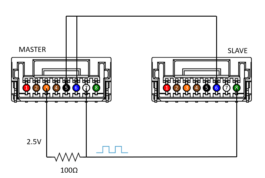
Instead of using an external trigger signal, the user can use a master camera’s strobe output to trigger one or many slave cameras to achieve synchronous capture.
The following is an example setup with one master and one slave Phoenix:
In ArenaView, configure the following.
- Turn on VCC output on the master camera. Refer to VCC section in this application note.
- Turn on strobe output on the master camera. Refer to Setting Up Strobe Output section in the application note.
- Turn on trigger input on the slave camera. Refer to Trigger Configuration section in the application note.
Jitter and Delay
In many high precision tasks, jitter and delay are two common characteristics system designers care about in order to guarantee a certain precision in their inspection task. Knowing the jitter and delay values helps the system designer to understand the accuracy in device operational sychronization.
To measure the jitter and delay of LUCID cameras, you can use an oscilloscope and two probes. Follow the steps below.
- Set Exposure Auto to Off and Exposure Time to a fixed exposure time, such as 500µs .
- Put the camera in trigger mode. Refer to Trigger Configuration section in the application note.
- Configure strobe output on the camera. Refer to Setting Up Strobe Output section in the application note.
- Attach a probe to your trigger signal pins and another probe to the camera’s strobe output pins.
- On the scope, the trigger signal and strobe signal can be shown at the same time. Measure the difference between trigger activation edge and strobe output edge.
How fast the camera responds to the trigger signal could depend on the following parameters:
- Camera interface
- Sensor resolution
- Sensor trigger mode
- Type of I/O signal
- Voltage of the trigger signal
- Active flange for the trigger
- Signal quality (noise, slew rate)
The following jitter and delay values were measured on specific camera models with specific firmware. These values may change depending on firmware version and mode of camera operation. Please refer to the value below for comparison with your actual setup.
| Camera | Firmware Version | Input Signal (V) | Offset (V) | Trigger Freq (Hz) | Exposure Time (μs) | Min Latency (μs) | Max Latency (μs) | Jitter (μs) |
|---|---|---|---|---|---|---|---|---|
| PHX004S | 1.5.0.0 | 5.00 | 2.50 | 1.00 | 500.00 | 13.40 | 18.60 | 5.20 |
| PHX016S | 1.5.0 .0 | 5.00 | 2.50 | 1.00 | 500.00 | 24.60 | 36.20 | 11.60 |
| PHX032S | 1.5.0.0 | 5.00 | 2.50 | 1.00 | 500.00 | 35.00 | 50.60 | 15.60 |
| PHX050S | 1.5.0.0 | 5.00 | 2.50 | 1.00 | 500.00 | 41.40 | 60.60 | 19.20 |
| PHX050S-P | 1.6.0.0 | 5.00 | 2.50 | 1.00 | 500.00 | 41.00 | 60.60 | 19.60 |
| PHX089S | 1.5.0.0 | 5.00 | 2.50 | 1.00 | 500.00 | 67.80 | 100.20 | 32.40 |
| PHX120S | 1.5.0.0 | 5.00 | 2.50 | 1.00 | 500.00 | 67.40 | 99.40 | 32.00 |
Trigger Latency Feature
LUCID has implemented a featured named Trigger Latency to allow more deterministic trigger behavior. When this feature is enabled, the trigger latency will be fixed and the jitter will be significantly smaller.
To turn on the feature, set Trigger Latency = One Line
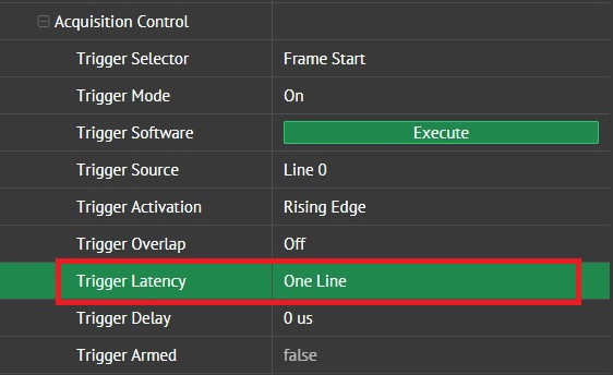
With Trigger Latency set to One Line, the following measurements were captured on a PHX050S-PC (IMX250MZR): Trigger Latency is ~61 microseconds and Jitter is typically <100 nanoseconds.
Summary
There is no single solution of using GPIO that fits every application. The most suitable solution (ie. Using Optocoupled pin or not) depends on the application need. The following table shows a quick summary of optocoupled versus non-optocoupled input/output pins.
| GPIO | Opto-coupled | |
|---|---|---|
| Speed | ++ | + |
| Over-voltage protection | + | ++ |
| Flexible direction | + | – |
| Functionality | ++ | + |
| Robust | + | ++ |
| Electrical isolation | – | + |
| Shortcut protection | – | + |
| Slew rate / short pulses | ++ | – |
Glossary
| Strobe | Output signal generated by the camera’s exposure, can be used to trigger flash or general illumination. |
| Trigger | Signal used to start the image capture. |
| Opto-coupler | Device to split circuits electrically. |
| GPIO | General purpose input or output pin, direction is configurable by software. Functionality is also independent. |
| VCC | Voltage at the common collector. |
| GND | Ground. GND is the reference point from which voltages are measured for the non-optocoupled pins. |
| TTL | True Transistor Logic. Digital communication with 5 Volt level. |
| Free-run mode | The camera sends a continuous stream of images. Also called live, streaming or video mode |
| Snapshot Mode | Taking a single image under “single acquisition” mode after application command. One frame is captured. |
| Trigger mode | Mode for capturing a single image, also called snapshot or capture mode |
Table of Contents
Introduction
Prerequisites
Free-Run Mode
Snapshot Mode
Trigger Mode
Cable & Connector Info
Phoenix GPIO Info
Triton & Atlas GPIO Info
GPIO Pin Map & Function
Trigger Configuration
Over Trigger
Multi-frame Trigger
Setting up Strobe Output
Opto-isolated Strobe Output
VCC Voltage Output
Synchronous Capture – Master/Slave
Jitter and Delay
Trigger Latency Feature
Summary
Glossary