 Support Center
I2C Support on LUCID Cameras
Introduction
This document will discuss using Inter-Integrated Circuit (I2C) communication with LUCID cameras.
Equipment Used
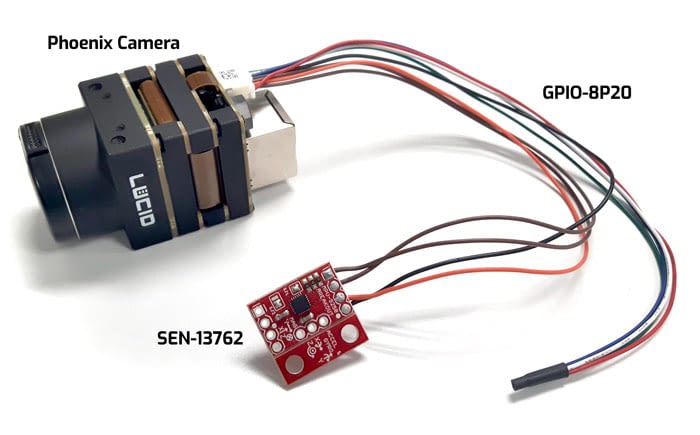
- PHX032S, Phoenix 3.2MP Sony IMX265, firmware 1.29.0.0
- GPIO-8P20, 8-pin 20cm JST cable
- SEN-13762, SparkFun IMU Breakout – MPU-9250 Board (DigiKey: 1568-1420-ND)
- Arena SDK for Windows v1.0.9.1 or newer
Function Summary
In LUCID’s I2C implementation, the non-opto isolated pins (Line 2 and Line 3 on Phoenix) can be used for the I2C Serial Clock (SCL) and I2C Serial Data (SDA) pins.
The camera features I2C Register Address and the I2C Slave Address can be configured to configure the register address to read and the slave address to use.
- The I2C Register Address Length can be 8-bits (0 – 0xFF) or 16-bits (0 – 0xFFFF)
- The I2C Slave Address Length can be 7-bits (0 – 0x7F)
I2C Example Setup
The following diagram shows connecting the Phoenix GPIO to a Sparkfun IMU Breakout board with an MPU-9250 sensor.
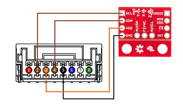
The following connections are shown in the above images:
| Phoenix GPIO Pin | Description | SEN-13762 |
|---|---|---|
| Pin2 (Brown) | Non-isolated bi-directional GPIO channel (Line2) | SCL |
| Pin4 (Brown) | Non-isolated bi-directional GPIO channel (Line3) | SDA |
| Pin3 (Orange) | VDD GPIO (2.5V Power Output) (Line 4) | VDD |
| Pin5 (Black) | GND (Camera GND) | GND |
Specifications Tested:
- SCL / I2C serial clock: 400 kHz
- Voltage: 5V
Reading with I2C
The following registers will be read from the MPU-9250 sensor (https://www.invensense.com/download-pdf/mpu-9250-register-map/):
| Address (Hex) | Register Name | Description | Length (bits) |
|---|---|---|---|
| 3B | ACCEL_XOUT_H | Accelerometer X-Axis high bytes | 8 |
| 3C | ACCEL_XOUT_L | Accelerometer X-Axis low bytes | 8 |
| 3D | ACCEL_YOUT_H | Accelerometer Y-Axis high bytes | 8 |
| 3E | ACCEL_YOUT_L | Accelerometer Y-Axis low bytes | 8 |
| 3F | ACCEL_ZOUT_H | Accelerometer Z-Axis high bytes | 8 |
| 40 | ACCEL_ZOUT_L | Accelerometer Z-Axis low bytes | 8 |
The I2C Slave Address will be 0x68 (https://learn.sparkfun.com/tutorials/mpu-9250-hookup-guide).
The following pseudocode demonstrates reading the values from the MPU-9520 sensor:
// Connect to camera// Get device node map// Turn on VoltageExternalEnable (GPIO VDD)Set LineSelector = Line4;VoltageTageExternalEnable = True;I2CSlaveAddress = 0x68;I2CSCLSource = Line2;I2CSDASource = Line3;I2CAccessLength = 1; // Read 1 byte at a time// Set I2C Read OperationI2COperationSelector = Read;// Read ACCEL_XOUT_HIGHI2CRegisterAddress = 0x3B;I2COperationExecute();// Confirm I2COperationStatus == SuccessACCEL_XOUT_HIGH = I2CAccessBuffer // Read 1 byte out of I2CAccessBuffer// Read ACCEL_XOUT_LOWI2CRegisterAddress = 0x3C;I2COperationExecute();// Confirm I2COperationStatus == SuccessACCEL_XOUT_LOW = I2CAccessBuffer // Read 1 byte out of I2CAccessBuffer// Read ACCEL_YOUT_HIGHI2CRegisterAddress = 0x3D;I2COperationExecute();// Confirm I2COperationStatus == SuccessACCEL_YOUT_HIGH = I2CAccessBuffer // Read 1 byte out of I2CAccessBuffer// Read ACCEL_YOUT_LOWI2CRegisterAddress = 0x3E;I2COperationExecute();// Confirm I2COperationStatus == SuccessACCEL_YOUT_LOW = I2CAccessBuffer // Read 1 byte out of I2CAccessBuffer// Read ACCEL_ZOUT_HIGHI2CRegisterAddress = 0x3F;I2COperationExecute();// Confirm I2COperationStatus == SuccessACCEL_ZOUT_HIGH = I2CAccessBuffer // Read 1 byte out of I2CAccessBuffer// Read ACCEL_ZOUT_LOWI2CRegisterAddress = 0x40;I2COperationExecute();// Confirm I2COperationStatus == SuccessACCEL_ZOUT_LOW = I2CAccessBuffer // Read 1 byte out of I2CAccessBuffer
Writing with I2C
The following registers will be read from the MPU-9250 sensor (https://www.invensense.com/download-pdf/mpu-9250-register-map/):
| Address (Hex) | Register Name | Description | Length (bits) |
|---|---|---|---|
| 0D | SELF_TEST_X_ACCEL | Accelerometer X-Axis high bytes | 8 |
| 0E | SELF_TEST_Y_ACCEL | Accelerometer X-Axis low bytes | 8 |
| 0F | SELF_TEST_Z_ACCEL | Accelerometer Y-Axis high bytes | 8 |
The I2C Slave Address will be 0x68 (https://learn.sparkfun.com/tutorials/mpu-9250-hookup-guide).
The following pseudocode demonstrates writing values to the MPU-9520 sensor:
// Connect to camera// Get device node map// Turn on VoltageExternalEnable (GPIO VDD)Set LineSelector = Line4;VoltageTageExternalEnable = True;I2CSlaveAddress = 0x68;I2CSCLSource = Line2;I2CSDASource = Line3;I2CAccessLength = 1; // Write 1 byte at a time// Set I2C Write OperationI2COperationSelector = Write// Write 0x01 to SELF_TEST_X_ACCELI2CRegisterAddress = 0x0D;I2CAccessBuffer = 0x01;I2COperationExecute();// Confirm I2COperationStatus == Success// Write 0x01 to SELF_TEST_Y_ACCELI2CRegisterAddress = 0x0E;I2CAccessBuffer = 0x01;I2COperationExecute();// Confirm I2COperationStatus == Success// Write 0x01 to SELF_TEST_Z_ACCELI2CRegisterAddress = 0x0F;I2CAccessBuffer = 0x01;I2COperationExecute();// Confirm I2COperationStatus == Success// Read SELF_TEST_X_ACCELI2CRegisterAddress = 0x0D;I2COperationExecute();// Confirm I2COperationStatus == SuccessSELF_TEST_X_ACCEL = I2CAccessBuffer // Read 1 byte out of I2CAccessBuffer// Read SELF_TEST_Y_ACCELI2CRegisterAddress = 0x0D;I2COperationExecute();// Confirm I2COperationStatus == SuccessSELF_TEST_Y_ACCEL = I2CAccessBuffer // Read 1 byte out of I2CAccessBuffer// Read SELF_TEST_Z_ACCELI2CRegisterAddress = 0x0D;I2COperationExecute();// Confirm I2COperationStatus == SuccessSELF_TEST_Z_ACCEL = I2CAccessBuffer // Read 1 byte out of I2CAccessBuffer
Phoenix GPIO Characteristics
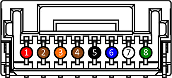
GPIO connector as seen from rear PHX050S view. Pin colors correspond to GPIO-8P20 cable from Lucid Vision Labs.
| Pin Number | Pin Description |
|---|---|
| 1 (Red) | VAUX (12-24V DC Power Input) |
| 2 (Brown) | Non-isolated bi-directional GPIO channel (Line 2) |
| 3 (Orange) | VDD GPIO (2.5V Power Output) (Line 4) |
| 4 (Brown) | Non-isolated bi-directional GPIO channel (Line 3) |
| 5 (Black) | GND (Camera GND) |
| 6 (Blue) | OPTO GND (Opto-isolated Reference) |
| 7 (Yellow) | OPTO OUT (Opto-isolated Output) (Line 1) |
| 8 (Green) | OPTO IN (Opto-isolated Input) (Line 0) |
I2C Access Control Nodes
| Node Name | Description |
|---|---|
| I2COperationSelector | Selects the target operation for the I2C communication on the device. This operation is executed when the I2COperationExecute feature is called. |
| I2COperationExecute | Executes the operations selected by I2COperationSelector on the I2C communication. |
| I2CAccessBuffer | Defines the intermediate access buffer that allows the exchange of data between the device’s I2C communication and the application. |
| I2CRegisterAddress | Controls the register address for the operation selected by the I2COperationSelector. |
| I2CRegisterAddressLength | Controls the register address length used for the I2C communication. |
| I2CAccessLength | Controls the number of bytes to transfer to or from the I2CAccessBuffer. |
| I2COperationStatus | Represents the I2COperationExecute status. |
| I2COperationResult | Represents the number of successfully read/written bytes for the I2C operation. |